• If You Are Having Trouble Logging In with Your Old Username and Password, Please use this Forgot Your Password link to get re-established.
  • Hey! Be sure to login or register!

New kid on the block - Smith Cub

Electrical / Avionic and the like...Part 1

The dreaded electrical system!!!

I never could understand electricity, I just don’t know why but it always been like this. For some guys it is just natural but for me it is a nightmare. Volts, Amps, Ohms are not the guys I used to hang around with. So in order to educate myself I started by reading ‘’The Aero Electric Connections’’ by Bob Nuckolls. Very well written with lots of explanatory diagrams, exactly what I needed! Also a bunch of articles about basic electrical written by Ron Alexander, all very instructive for a beginner like myself. So to make a long story short here are some pointers given by Ron before starting cutting wires:


  • Determine what electrical equipment you want to install
  • Locate these components within the aircraft structure
  • Locate your battery, bus bars, and circuit breaker panels
  • Protect the components by determining proper wire size and circuit breaker/fuse requirements
  • Connect component parts to an adequate power source
  • Ground and bond necessary items
  • Install proper instrumentation to monitor the system
  • Draw a detailed schematic of the system for reference

So in order to begin this section of the project I needed to determine what I wanted for instruments. Having flown on machines that only had primary flight display (PFD) and multi-function display (MFD) as reference, I decided to go that route, so no steam gauges.

Here is the list of equipment that will be installed in this aircraft:

  1. ILEVEL 3AW: It provides ADS-B Weather & traffic information, GPS navigation, AHRS and DATA Recording. It is portable and WI-FI
  2. GRT - Engine Information System / Model 4000: Displays all information needed for the engine and more. Also this EIS is wired to the ILEVEL and connect to the IPAD
  3. IPAD PRO 10.5 inch for AHRS and NAV
  4. IPHONE for EIS display information
  5. KT-6A Transponder
  6. KY-97A COMMS
  7. PM1200 Intercom
  8. BLUE SEA Systems for distribution Bus
  9. EARTH X – ETX 680C Battery
  10. Plane Power 70 Amp Alternator…This alternator came with the engine that I bought. I’ll be able to hang Christmas lights all over the aircraft for night flying.

NOW, this is where I will need you guys to point me in the right direction because it is not my field of expertise!!
Here is my attempted schematic of the system:

IMG_1245.jpg


12 Volts system with:

  • LAMAR 12 VOLT CONTINOUS DUTY
  • LAMAR 12 VOLT INTERMITTENT DUTY
  • CESSNA Type split rocker master switch
  • ACS A-510-2 Ignition switch


Also according to the wire size chart I made a list of the circuit protection requirements for all the equipment planned for this project.

IMG_1247.jpg

IMG_1248.jpg

IMG_1249.jpg

So, once again Gents, if you have a chance, please review this and just go ahead with your suggestions / comments.
More to follow!
Dan
 

Attachments

  • IMG_1245.jpg
    IMG_1245.jpg
    129 KB · Views: 1,338
  • IMG_1247.jpg
    IMG_1247.jpg
    110.7 KB · Views: 1,340
  • IMG_1248.jpg
    IMG_1248.jpg
    93.7 KB · Views: 1,334
  • IMG_1249.jpg
    IMG_1249.jpg
    69 KB · Views: 1,338
Get rid of the 70 amp breaker feeding the fuse boxes. Not sure what it's for. The path of main bus power from the master relay to the bus should be a single wire. If there are 'problems' with that circuit, you can just switch off the master switch.

If you stay with the Plane-Power alternator, I'd switch to a 50 amp push-pull breaker. You'll never pull 50 amps from that unit and if there is a short circuit, the breaker is resetable. If you have no amp shunt installed the path of power for the alternator output is from the output terminal, to the 50 amp breaker, to the main bus (main fuse box for you). If you install an amp shunt, the path of power is from the output terminal, to the 50 amp breaker, to the shunt (+), from the shunt (-) to main bus. This arrangement allows combination volt/ammeters to continue reading volts after the output breaker is pulled. Important if you find yourself running on battery alone.

Put a spike diode on all relays, not just the master.

Use a stud welded to the fuselage frame tubing for the battery ground. This insures the best integrity for grounds for any other circuits tied to airframe ground.

And REALLY important here. The size (gauge) of the wire is dependent on the length also, not just the amount of current it carries. For instance, if you need to power a circuit with a 5 amp breaker, you can use a 22 gauge wire until it exceeds 6 feet in length. Then you need to use 20 gauge wire, which is good until it exceeds 10 feet in length, etc. This is because there is a small amount of resistance in each length of wire. Smaller wire exhibits higher resistance to large amounts of current than larger wires (think water pumping through a small diameter pipe vs a large diameter pipe). So, if you use that 22 gauge wire at, say 20 feet in length, you get an excessive voltage drop. I.e., 12 volts applied to one end of the wire might end up only being 9 or 10 volts at the component. This can be calculated by Voltage = Amps X resistance (in Ohms).

And to throw another wrinkle in the wire chart, there are two charts in the AC43.13. One is for continuous duty circuits and the other is for intermittent duty circuits. An example of a continuous duty circuit would be nav lights. They come on and stay on. Examples of intermittent duty circuits would be a starter switch or strobes. The starter switch circuit is only energized for a few seconds at a time and the strobes are always turning on and off. So size the wire in accordance with the correct chart. That will allow you to use the smallest size wire which translates to easiest routing and lightest weight.

Web
 
Last edited:
Web,
Thank you very much for your inputs! Very good points about things that I simply did not know or didn't think of. I'll go back to the drawing board and amend it. If you see anything else or have other suggestions just don't hesitate!
Dan
 
There will be techniques and details to be worked out with the panel, instruments, and electrical systems. Why fuses instead of breakers? If it is to save panel space, consider Trig or Becker avionics instead of the tray mounted KT-76A and KY-97A stuff. Also look at 2 1/4" instruments for airspeed and altimeter, or experimental versions of units like the G5.

With all your electrical items in the panel area, weld in a tab for a ground stud, on the structure just forward of the panel. Make up a copper bar with two or three ground studs and fasten it to the tab. This gives you an electrically sound place to ground all of your instruments and avionics.

Power up items in the wings and tail, like nav lights or beacon, with shielded wire. If you use the center conductor(s) for power and the shield braid as ground, you can bring the grounds into the fuselage for attachment. This eliminates trying to make a ground path through painted/powder coated attach points or through hinges (like the rudder).

If you fab the wire harnesses for airframe or instruments/avionics, follow the manufacturer's diagrams. If you think you have a 'great shortcut' be sure to ask around before you do it. I've seen problems with rethinking audio and instrument harnesses.

Web
 
Web,

Once again, all good points!!

The question concerning breakers versus fuses: Is the weight, volume and cost of a breaker justified when a fuse will do the same basic job? In most instances, a breaker and fuse can be considered to be electrically equivalent; either device will provide the prescribed safety margin with respect to electrical fires. The best thing about these devices is ease of installation. In a matter of minutes, with the installation of a single component, you replace up to 20 breakers along with the work it takes to fabricate of bus bars and breaker panels. The Muli-Slot Plastic Fuseblock from Blue Sea will be easily accessible in the cockpit with spare fuses. That is why I chose fuses.

The KT-76A and KY-97A I already have ready to installed. I would prefer the smallest version of radio and transponder but I will direct the $3000 + money for these gizmos somewhere else :lol:

Dan
 
Are you planning to use the fuses for switches as well? C/Bs can double as switches further simplifying the installation.
 
Are you planning to use the fuses for switches as well? C/Bs can double as switches further simplifying the installation.

Rocker switches.
Here is an idea of the panel I'm sort of thinking about:

Instrument Panel Template.jpg

Dan
 

Attachments

  • Instrument Panel Template.jpg
    Instrument Panel Template.jpg
    148.7 KB · Views: 1,047
Take a look at these: https://amironic.co.il/products/circuit-breakers/aircraft-circuit-breakers/20tc-series/
20tc.jpg

It took all of two minutes to find these.
 
I have been dealing with DC distribution for 30 years now - 12, 24 and 48V. When I was young and dumb I used a lot of fuses. As I learned and gained experience, I haven't used a fuse in years. Just about any breaker is better than a fuse. Blue Sea fuse panels I used to buy 50-100 at a time. Over the last 10 years I have been pulling more and more out after they've failed. I haven't done a mass replacement push yet, but as they fail, I replace them with a re settable breakers.

On grounding, nothing can mess up a great installation like poor grounding. Grounding is often the hardest part and is treated as a afterthought when things don't function as expected. Pre-planning the grounding and testing (before you say it's good!) will save a lot of head scratching later.
 
Last edited:
Cutting out the Instrument Panel

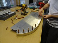
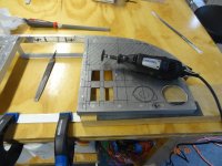
Now that I have an instrument panel layout plan...May as well start to cut pieces out of it. It would have been nice to use a CNC machine for that job! Pretty time consuming with a dremel and a file! :wink:

082(a).jpg 085.JPG

086.JPG 087.jpg
I added a lip instead of brackets to the panel so that the top cowling would have better support.

088 (18).jpg 088 (23).JPG

088 (34a).jpg 088 (4).JPG
I bought a Guardian IPAD Pro 10.5 Inch panel mount and made a frame for it.

088 (8).jpg 088 (50).JPG
Then I made brackets for the radio & transponder trays as well as for the PM1200 Intercom.

088 (60).JPG
Taking shape.

088 (13).JPG 088 (14).JPG 088 (43).jpg
Making of the IPAD cover

088 (62).jpg 088 (63).JPG
I really wish that I had been using a CNC Machine!

089 (3).JPG
All done!

More to follow!
Dan
 

Attachments

  • 082(a).jpg
    082(a).jpg
    157.8 KB · Views: 851
  • 085.JPG
    085.JPG
    153.7 KB · Views: 121
  • 086.JPG
    086.JPG
    122.7 KB · Views: 110
  • 087.jpg
    087.jpg
    63.2 KB · Views: 116
  • 088 (18).jpg
    088 (18).jpg
    88.5 KB · Views: 125
  • 088 (23).JPG
    088 (23).JPG
    145 KB · Views: 114
  • 088 (34a).jpg
    088 (34a).jpg
    63 KB · Views: 108
  • 088 (4).JPG
    088 (4).JPG
    140.8 KB · Views: 129
  • 088 (8).jpg
    088 (8).jpg
    83 KB · Views: 129
  • 088 (50).JPG
    088 (50).JPG
    160.8 KB · Views: 111
  • 088 (60).JPG
    088 (60).JPG
    173.6 KB · Views: 127
  • 088 (13).JPG
    088 (13).JPG
    130 KB · Views: 114
  • 088 (14).JPG
    088 (14).JPG
    128.7 KB · Views: 129
  • 088 (43).jpg
    088 (43).jpg
    64.7 KB · Views: 124
  • 088 (62).jpg
    088 (62).jpg
    85.2 KB · Views: 109
  • 088 (63).JPG
    088 (63).JPG
    171.4 KB · Views: 108
  • 089 (3).JPG
    089 (3).JPG
    222.1 KB · Views: 134
Hate to be a stickler about stuff, but a PM 1200 is made to be mounted directly to the instrument panel without a tray or a cutout. It comes with a paper pattern that shows hole sizes and locations so that (with knobs removed) the box is installed from the back of the panel, the face plate is held on the front of the panel, and the screws are installed, holding them together.

Have you checked the fit of those avionics trays with the boot cowl?

Web


Web,
I think I'll be wearing a cup soon! Hahaha!!!
All joking aside, thanks for checking on me!
You're right about the PM1200. See the picture below, mine is wrapped with a thin layer of foam and inserted into a little case that has a door that opens downward for easy access and removal.
107 (8a).jpg

Avionic trays checked for clearance...All is good so far!

Dan
 

Attachments

  • 107 (8a).jpg
    107 (8a).jpg
    227.5 KB · Views: 836
And I'm sure that you've found out that cutting square holes is more time consuming than drilling round ones,:lol:

Web
 
Drill holes for W31 series switch breakers and punch holes for instruments and radios. Works much gooder.

Web
 
Electrical / Avionic and the like...Part 2

I have concluded that I could not attach all the goodies on the instrument panel so a platform to support most of them was in order.

070 (3).jpg 070 (4).jpg
Material 2024-T3 ( .032)

001a.jpg 002a.jpg

005a.jpg 004a.jpg
I also decided that the GRT EIS does not need to be in view because it is wi-fi and link to the IPAD & IPhone. So it was installed right behind the IPAD location on the platform. Easier to access it for troubleshooting.

001.JPG 002.JPG

003.JPG 012A (2).jpg

006.JPG 014.jpg
Now for the ILevel 3AW, it needs a surface that will be leveled when the airplane is in the air during a level flight. In order to do so, I made some sort of a monopod tilt head in order to adjust accurately the position of this 3-axis accelerometer. It is also attach to the platform.

015 (1).JPG
Getting closer to the wiring task :wink:

Dan
 

Attachments

  • 070 (3).jpg
    070 (3).jpg
    112.1 KB · Views: 2,032
  • 070 (4).jpg
    070 (4).jpg
    112.2 KB · Views: 1,651
  • 001a.jpg
    001a.jpg
    141.8 KB · Views: 163
  • 002a.jpg
    002a.jpg
    122.5 KB · Views: 161
  • 005a.jpg
    005a.jpg
    115.3 KB · Views: 168
  • 004a.jpg
    004a.jpg
    142.4 KB · Views: 161
  • 001.JPG
    001.JPG
    119.5 KB · Views: 150
  • 002.JPG
    002.JPG
    111 KB · Views: 156
  • 003.JPG
    003.JPG
    126.9 KB · Views: 153
  • 012A (2).jpg
    012A (2).jpg
    66.5 KB · Views: 157
  • 006.JPG
    006.JPG
    128.9 KB · Views: 185
  • 014.jpg
    014.jpg
    83.9 KB · Views: 157
  • 015 (1).JPG
    015 (1).JPG
    159.2 KB · Views: 1,682
You're way overthinking mounting stuff on the instrument panel. You will end up with a heavier and more time consuming panel as a result. What thickness aluminum is the panel? I rarely use thicker than .040" on Cub panels and usually use a stock blank panel (.032" soft?). The bottom edge of the panel is usually bent to a 90º angle. If you leave that bend in place when you make the center cut out, you can simply install a vertical rail on each side of the cut and you're done.

Question about your ILevel unit; Does it need to be leveled at each flight? If not, pick a spot up/forward from the panel and mount it level while the fuselage is leveled. Once it's leveled and secured in place, it should not require further 'fiddling'.

Keep stuff simple. The more complicated the install becomes, the more complicated maintenance becomes, in the future. The sanity you save may be your own.

Web
 

You're way overthinking mounting stuff on the instrument panel. You will end up with a heavier and more time consuming panel as a result. What thickness aluminum is the panel?
Web
Dan,
Are you building a bridge? The thickness of those aluminum angles are way over done. You could reduce their weight by at least 2/3.
 
Web, It is too late now...This is what happen when you are retired and have lots of time to think things over and over...I might be losing it, HELP :yikez:!!!
 
Don't be afraid to start over. You have a raw panel there, right now. If you don't think something turned out the way YOU want it, back up and make it right. Maybe buy a blank panel to use as your starting point. I don't want you to stop building, or even build something that 'we' tell you to. I want you to understand that even experimental aircraft are better when light and simple. And starting with a new panel now is better than climbing into your aircraft every day for the next thirty years, groaning when you see the panel. Again.

Web
 
You would be amazed at how strong an angle is when bent from a piece of 2024-T3 .025" or .032". In this application anything thicker is overkill.
 
Back
Top