• If You Are Having Trouble Logging In with Your Old Username and Password, Please use this Forgot Your Password link to get re-established.
  • Hey! Be sure to login or register!

O-320 Crankshaft broke in half...

Alpha Romeo

MEMBER
Vernonia, OR
Long time reader. First time poster here.

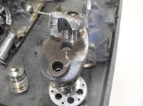
Had an engine failure in my PA-12 O-320. In flight 3 miles from my home airport developed severe engine knock and loosing power. No symptoms leading up to it, just sudden knock. Very blessed to make it home safely.

Had an engine shop tear down the engine and found that I now have a 2 piece crankshaft. Broke all the way through at the center main bearing. Does anyone know why or how this could have happened? I will try to attach pictures.

Also I am trying to locate a replacement crankshaft. If someone could point me in the correct direction I would really appreciate it. I posted an add in the classified section.

15289 035.jpg15289 034.jpg15289 036.jpg
 

Attachments

  • 15289 035.jpg
    15289 035.jpg
    108.7 KB · Views: 312
  • 15289 034.jpg
    15289 034.jpg
    111.6 KB · Views: 219
  • 15289 036.jpg
    15289 036.jpg
    79.6 KB · Views: 475
Times on engine? Times on crank? What was the full model number of the O-320? Mags or electronic ignition?

Web
 
325 since field overhaul. Unknown time on crank. Engine shop that tore it down said it looked like it was from the 60's (not sure how they could tell that). This is a O-320 B2A that was put on this plan in the 70's and overhauled in the late 90's. Mags
 
Was it a 160hp engine…was there a yellow tag from last OH for the crank? Not all cranks pass to be 160 hp engines I remember being told by AVEMCO.
 
It is a 160hp. I will have to dig through the books and see what I can find about the crank during the overhaul.
 
Was it a 160hp engine…was there a yellow tag from last OH for the crank? Not all cranks pass to be 160 hp engines I remember being told by AVEMCO.

SB 505 (1997) I think is what you are referring to.
deals with allowable tolerance due to corrosion in nose of crank.
O 320
150 hp 1.920 ID
160 hp 1.910
unrelated to crank journal failure described above.
 
The center main takes a real pounding in these 4 cyl opposed engines. Under the heading of wild speculation with insufficient data to support any of it, my best guess would be that your case was likely not overhauled during the field overhaul and was out of spec at the center main allowing the crank to flex at the center main, ultimately leading to failure. But at this point in time, your case is probably wallowed out so bad that it would be impossible to get any kind of meaningful measurement to prove it out. My question would be whether the case was overhauled and brought back to new spec during the field overhaul, or whether they gave it a pass while overhauling the crank and replacing the bearings? Even if the case wasn't overhauled, while that would support my speculation of the case being out of spec, that doesn't necessarily mean that it was.

Thanks for sharing.

-Cub Builder
 
My guess is an old unrecorded prop strike. I had one go about 300 hours after running into a wind tee. It was on a rod bearing, and other than increased noise I had no idea what happened.

Flew back to the airport, turned it on a few more times, then in desperation I started pulling cylinders and rods. Went to wipe a hair off a polished journal, and there it was.
 
You’ll need a microscope/magnifier to see the fine details of the fractured surface. I don’t have an example picture to show you what to look for. One thing you’ll be looking for is crack propagation that looks similar to growth rings on a tree….you may find very very fine rings/ridges. A good metallurgist can follow the signs with an odd looking microscope to identify where the crack started. I’d lay good odds on a journal or fillet not polished smooth or was scratched by accident or hard foreign debris cause a scratch…scratches on a surface not polished adequately after grinding can create the initial flaw leading to creating a crack especially in the fillet area if isn’t polished smooth. It may be worth the expense to have the crankshaft inspected by a metallurgist who has a history of working with insurance adjusters giving you recourse to offset the cost if the machine shop or engine builder created the problem.


Sent from my iPad using Tapatalk Pro
 
Something like this:

05062405m2.jpg
 
Glad you made it home safe with only an engine to worry about fixing.

My thanks to all with suggestions and reasons why it may have cracked, good things to consider when we consider our options when working on our engines.

Little things do make a difference!
 
You’ll need a microscope/magnifier to see the fine details of the fractured surface. I don’t have an example picture to show you what to look for. One thing you’ll be looking for is crack propagation that looks similar to growth rings on a tree….you may find very very fine rings/ridges. A good metallurgist can follow the signs with an odd looking microscope to identify where the crack started. I’d lay good odds on a journal or fillet not polished smooth or was scratched by accident or hard foreign debris cause a scratch…scratches on a surface not polished adequately after grinding can create the initial flaw leading to creating a crack especially in the fillet area if isn’t polished smooth. It may be worth the expense to have the crankshaft inspected by a metallurgist who has a history of working with insurance adjusters giving you recourse to offset the cost if the machine shop or engine builder created the problem.


Overhauled in the late 90s. Good luck finding anyone to seek recourse on.
Unless the crank was turned down to an “undersize” at overhaul then the last to machine it was the factory 60+ years ago
Magnifluxing is required at overhaul so any external crack would have shown up then. Did a prop strike occur after that?

This is a narrow deck engine as the crank has the lightening holes in the flange; which ended in the mid 60s when the wide deck was introduced.
Previous prop strike? Possible…. Usually the crank flanges on those would easily get bent or would crack between the holes as a result.

In earlier years prop strikes did not require a teardown inspection. Just dial the flange, if ok, swap the prop and move on.

Ive never seen an O-320 crank come apart. (Unless in a major wreck)
 
Cub builders photo shows pretty classic fatigue. That one started from an initiation point somewhere in the upper left area of the crack. It was potentially cracked for awhile and has a fairly large area of fatigue ending when there was not enough material and it failed the rest of the way all at once from overload. We do this kind of analysis at my job. Initiation points can come from a number of things. A nick in the surface, an inclusion in the forging, poor machining, other things, can all initiate a crack. Sometimes a design is robust enough to tolerate small surface cracks. Other times, the best you can hope for is to find the crack and replace the part before it's final overload failure. Failure analysis usually takes microscopy, training, and experience to do a good job and even then, I would say you don't get an absolute answer about half the time. You are looking for very small signs in the steel. It is possible to make some guesses based upon high probability events. In this case, just based upon probability, I would guess a small nick at the surface or an inclusion near the surface initiated a crack. Sometimes, a crack can initiate at an anomaly under normal loads. Sometimes it takes some kind of initiating event like a prop strike or an overheat of some kind. Holes, like in the photo, also tend to focus that stress as you can see on the example above.

Wayne

What are the differences in indicators between a crack developing over time and one that develops from a single incident such as a prop strike? Specifically in a casting such as a crank.

Web
 
Look for a thumbnail looking feature. Typically associated with the crack initiation point. Appears the thumbnail feature is at the tip of the image in skywagin8a post. Possibly an oil channel?
 
..... It may be worth the expense to have the crankshaft inspected by a metallurgist ... giving you recourse to offset the cost if the machine shop or engine builder created the problem.

Good luck proving that after 20+ years,
esp if you didn't hire the overhaul done yourself and/or own the airplane that whole time.
Sometimes **** just happens.
 
Got to thinking about another potential high stress shock to a crank.

The narrow deck engines originally were produced with 7/16 inch valve stems vs the 1/2 inch used now. Those were taken out of service and converted to the larger type as several were breaking the valve heads off.

When that happens the cylinder becomes a steel crusher. The head and piston can look like someone took an ax or large hammer to it. Quite scary!

That kind of force is directed strait to the crank journals.
Perhaps this engine was one to experience that in its early years???
 
One possibility of the cause of this breakage could have been a vibrational resonance was somehow induced in the engine, which just happened to concentrate where the crank broke? This could have been a vibration which the pilot would have never felt. Perhaps the prop blades were not set at exactly the same angle to each other, for example? This could set up a resonance which the crankshaft did not like? There are all sorts of things which set up resonances in airplanes and engines which, if felt, could be very difficult to locate. Even when you feel them they are hard to find. The list of possibilities is endless.

Another thing to notice, though not necessarily the cause of the crank breaking, is the narrow deck engines had a tendency for the case halves to fret on each other. Look again at this picture, notice the black surface where the two halves join at the center bearing saddle and at the rear half of where the front bearing is joined. That black surface means the two crankcase halves have been moving against each other, wearing away materiel. At the very least this crankcase needs to be resurfaced. There is also a dowel modification which is supposed to prevent this fretting, which has not been installed in this case.

View attachment 60762
 
Prop balancer locally has said exactly what sky notes above. Also a local Cub w/narrow deck O-320 has had periodic lower front case seeps of oil. They periodically tighten the case bolts and apply goop to arrest the leaks. Older cub that came from the game guiding world with a series of long props. Not my ride however.

Gary
 
What are the differences in indicators between a crack developing over time and one that develops from a single incident such as a prop strike? Specifically in a casting such as a crank.

Web
A crack over time will normally be a function of fatigue. Fatigue fractures all have an appearance of the lines on a beach where the water has washed up, usually a series of curved lines which you can see pretty well in cub builders photo above. You have an initiation point(sometimes multiple) which then grow with a number of what we commonly call beach marks more or less curving out from the initiation sight. At some point, the fatigue has gone far enough that you no longer have the strength required and the part falls the rest of the way in overload. The overload section will often look kind of dimpled although you might need a microscope to see it. In cub builders photo, you can definitely see a difference as you work across the fracture surface. Starting from the upper left, you can see fairly fine textured beach marks that get slightly coarser as you work down and to the right. That is all the fatigue fracture zone. After you get closer to the edge towards the lower left, you can see a definite change in the texture. The beach marks all disappear and it's kind of more frosty. That's the final overload fracture zone which happened pretty much all at once. It's a little hard to describe in words and still be anything anybody might want to read, I'm finding. :-? So part of what I'm saying is that I would expect a single incident like a prop strike to be the initiation for the fatigue. A fracture that fails suddenly will not typically have beach marks and will look quite different. I would expect it would take a lot more than your typical prop strike to fail a crank immediately. It can be very difficult to tell precisely the initiation cause because the fracture surfaces look very similar from one initiation cause to another. About the only easy one is some kind of inclusion in the steel that is still there to find.
Wayne
 
stoldriver wrote an excellent description of a fatigue failure fracture surface. Attached are two images of fatigue failures from ASM Metals Handbook of Fractography and Atlas of Microstructures, putting his words into pictures.

Fracture Image A.jpgFracture Image B.jpg
 

Attachments

  • Fracture Image A.jpg
    Fracture Image A.jpg
    55.9 KB · Views: 83
  • Fracture Image B.jpg
    Fracture Image B.jpg
    116.4 KB · Views: 68
Back
Top