
You are using an out of date browser. It may not display this or other websites correctly.
You should upgrade or use an alternative browser.
You should upgrade or use an alternative browser.
New kid on the block - Smith Cub
- Thread starter Buzzcola777
- Start date
Buzzcola777
MEMBER
Montreal, Canada
So being a newbie here with swing out engine mount, how does it work? You install brackets were the engine mount attachs to?
DJ
MEMBER
Bolivia
Do you need to support it with a hoist?The mount pivots on the stock bracket. Just pull the two bolts on the right and it opens to the left.
DENNY
Sent from my SM-G965U1 using SuperCub.Org mobile app
Buzzcola777
MEMBER
Montreal, Canada
Does anyone have a close-up photo of these stop brackets?
RaisedByWolves
FRIEND
Tx
No just make sure the stock exhaust doesn’t hit the boot cowl. It will dent it. The stop is there to prevent that but get removed when the Thrustline goes on
Sent from my iPhone using Tapatalk
Does anyone have a close-up photo of these stop brackets?
Reread the post, it is STOCK bracket not STOP bracket. http://www.javronaviation.com/Engine-Mount-Attachment-Bracket/ This is how you attach the engine mount to the fuselage with bolts. The bolts are vertical take two out of the right side and the mount hinges on the left. Original cubs had an extra bracket on the mount that would hold the mount out. Mine was removed in one of the many wrecks/rebuilds the plane has had a 9/16 box open end wrench will do the same stick the box in bracket and drop bolt through the open end wrench will hold the mount flange. In 3 point the weight of the engine will hold everything in place. https://www.univair.com/piper/piper...3b835SYFaFkCAmr81RJ4BoYZaJcJyB3gaAkohEALw_wcB has the bracket to hold it open.
DENNY
edit: That may be a bigger box open wrench than 9/16 Try a few use what fits.
Last edited:
Buzzcola777
MEMBER
Montreal, Canada
Reread the post, it is STOCK bracket not STOP bracket. http://www.javronaviation.com/Engine-Mount-Attachment-Bracket/ This is how you attach the engine mount to the fuselage with bolts. The bolts are vertical take two out of the right side and the mount hinges on the left. Original cubs had an extra bracket on the mount that would hold the mount out. Mine was removed in one of the many wrecks/rebuilds the plane has had a 9/16 box open end wrench will do the same stick the box in bracket and drop bolt through the open end wrench will hold the mount flange. In 3 point the weight of the engine will hold everything in place. https://www.univair.com/piper/piper...3b835SYFaFkCAmr81RJ4BoYZaJcJyB3gaAkohEALw_wcB has the bracket to hold it open.
DENNY
edit: That may be a bigger box open wrench than 9/16 Try a few use what fits.
Thanks for your post Denny,
Got it! Makes more sense now.
Dan
Buzzcola777
MEMBER
Montreal, Canada
Electrical / Avionic and the like...Part 5
I chose the Blue Sea Systems for this project:

ST Blade Fuse Block - 6 Circuits with Negative Bus and Cover

ST Blade Fuse Block - 6 Independent Circuits with Cover

Dual BusBar - 5 Circuit
The positionning of the fuse blocks will be on the left side of the cockpit.
.JPG")
.jpg")
Start with a drawing
.jpg")
First trial...
.JPG")
.jpg")
Couple modifications done to the side panel in order to get the box in.
.JPG")
Here are the blocks inside the side panel. By removing couple screws, I'll hace a quick access to the wiring dedicated to the fuses.

Also, the blade fuse lights up when it trips...Cool
More to follow
Dan
I chose the Blue Sea Systems for this project:
ST Blade Fuse Block - 6 Circuits with Negative Bus and Cover
ST Blade Fuse Block - 6 Independent Circuits with Cover
Dual BusBar - 5 Circuit
The positionning of the fuse blocks will be on the left side of the cockpit.
Start with a drawing
First trial...
Couple modifications done to the side panel in order to get the box in.
Here are the blocks inside the side panel. By removing couple screws, I'll hace a quick access to the wiring dedicated to the fuses.
Also, the blade fuse lights up when it trips...Cool
More to follow
Dan
Attachments
-
 5025.png43.8 KB · Views: 2,625
 -
 5035.png39.9 KB · Views: 2,650
 -
 2701.png33.8 KB · Views: 2,613
 -
 001 (5).JPG132.9 KB · Views: 172
 -
 001 (7).jpg73.6 KB · Views: 171
 -
 001 (10).jpg97.9 KB · Views: 165
 -
 001 (13).JPG145.1 KB · Views: 168
 -
 001 (15).jpg73.6 KB · Views: 169
 -
 002 (21).JPG165 KB · Views: 174
 -
 Glow fuses.jpg31.8 KB · Views: 2,600
Buzzcola777
MEMBER
Montreal, Canada
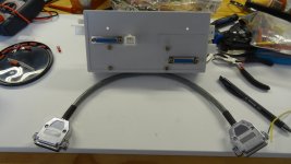
Electrical / Avionic and the like...Part 6
In order to eliminate wires crisscrossing behind the panels I have decided to bring everything that has something to do with electrical to a common place with a common ground. This common place is a junction box. Here is what I did...


First, draw a wiring diagram that icludes all components needed for Nav, Comms etc...

I colour coded these components for better references


So that I don't get loss with all the connections and wires, I made some sort of an Operator's Handbook for future references when repair is needed. Here are couple examples of it.
.JPG")
Here is the junction box with the molex connector as well as the DB-25s with the busbar. Mind you, it is a prototype...
.JPG")
What you see upper left is the Connection for the GRT Engine Information System, the Molex connector on it's right is the OAT (Data) + ILevel Grnd & Pwr and the DB-25 lower right has to do with EIS Fuel Press / Oil Press / Oil Temp /Voltmeter / Tachometer / Fuel Flow ans so on...
.JPG") Hundreds of printed labels for clarity.
Hundreds of printed labels for clarity.
.JPG")
SEE WHAT I MEAN...
.JPG")
.JPG")
The junction box will be attached to the component's platform right in front of the GRT EIS and hidden by the central Ipad. I think that I will eventually replace it with a circuit board...

I have mention earlier that I needed a common ground. This a drawing taken from Kitplanes Magazine written by Tom Wilson titled ''Posively Negative''. Very interestling...
More to follow...
Dan
In order to eliminate wires crisscrossing behind the panels I have decided to bring everything that has something to do with electrical to a common place with a common ground. This common place is a junction box. Here is what I did...
First, draw a wiring diagram that icludes all components needed for Nav, Comms etc...
I colour coded these components for better references
So that I don't get loss with all the connections and wires, I made some sort of an Operator's Handbook for future references when repair is needed. Here are couple examples of it.
Here is the junction box with the molex connector as well as the DB-25s with the busbar. Mind you, it is a prototype...
What you see upper left is the Connection for the GRT Engine Information System, the Molex connector on it's right is the OAT (Data) + ILevel Grnd & Pwr and the DB-25 lower right has to do with EIS Fuel Press / Oil Press / Oil Temp /Voltmeter / Tachometer / Fuel Flow ans so on...
Hundreds of printed labels for clarity.SEE WHAT I MEAN...
The junction box will be attached to the component's platform right in front of the GRT EIS and hidden by the central Ipad. I think that I will eventually replace it with a circuit board...
I have mention earlier that I needed a common ground. This a drawing taken from Kitplanes Magazine written by Tom Wilson titled ''Posively Negative''. Very interestling...
More to follow...
Dan
Attachments
-
 Junction Box 1.jpg116.8 KB · Views: 179
 -
 Junction Box 3.jpg159.5 KB · Views: 187
 -
 Wire Colour Code.jpg53.6 KB · Views: 191
 -
 DB-25 Connector 1.jpg70.1 KB · Views: 179
 -
 DB-25.jpg76.3 KB · Views: 184
 -
 Molex Connector.jpg79.9 KB · Views: 181
 -
 001 (4).JPG193.8 KB · Views: 176
 -
 001 (5).JPG195.7 KB · Views: 176
 -
 001 (7).JPG280.3 KB · Views: 440
 -
 001 (9).JPG291.5 KB · Views: 2,858
 -
 003 (1).JPG212.4 KB · Views: 194
 -
 001 (11).JPG230.4 KB · Views: 208
 -
 GROUND-5.jpg62.9 KB · Views: 186
Buzzcola777
MEMBER
Montreal, Canada
Wow, thats pretty cool. Very nice!!
Bill
Thanks Bill
RaisedByWolves
FRIEND
Tx
Does anyone have a close-up photo of these stop brackets?


Sent from my iPhone using Tapatalk
Buzzcola777
MEMBER
Montreal, Canada
RaisedByWolves,
Greatly appreciated!!
Thanks for the pics!
Dan
Greatly appreciated!!
Thanks for the pics!
Dan
Buzzcola777
MEMBER
Montreal, Canada
Electrical / Avionic and the like...Part 7
USB
Nowadays, a USB charging port is a must. I bought from the scrapyard a cigarette lighter socket assy for a buck and wired it so it can be integrated to instrument panel.
View attachment 52293 View attachment 52294

LANDING LIGHT
I don't really want to to cut an opening for the landing lights in the wing leading edge. On top of that, the price for the landing lights is astronomical! After looking around I stumbled upon this company by chance. RIGID is the company, made in USA. I choose to install the light on the landing gear cabane.

Small but very powerful. Model D-Series Pro #601213


Made a bracket to fix the light support.
For those who haven't see the promo video from RIGID, take a couple minutes to watch it. It is called: TORTURE - RIGID INDUSTRIES
INTERIOR LIGHTING
I intend to do some night flying with this aircraft. Without interior lighting it gets pretty dark in the cabin and if you drop something on the floor or anywhere else for that matter ... Well, you what I mean. LED lights have low heat emission and a low profile.

I made a drawing of the type and location of the LED lights. A potentiometer will be wired in order to dim the lighting system.
Using the 3D printer, a supports were printed for 2 different types of lights.
.JPG")
First support: long strip dedicated for cabin / Baggage area

.JPG")
3D printer doing its job!
.JPG")

LED strip light installed in its support. This light is located in front of the ILevel under the instrument panel.

.JPG")
You see here the support for the ILevel (back) and light in front.
.JPG")
.JPG")
Second support, a square one: Cabin upper & lower panels.

.JPG")
A long strip in the back and 2 square ones up front.
.JPG")
.JPG")
Couple squares in the upper baggage area. Also a view how it is installed on top.
.JPG")
...And 2 long strips in the lower baggage area.
More to follow!
Dan
USB
Nowadays, a USB charging port is a must. I bought from the scrapyard a cigarette lighter socket assy for a buck and wired it so it can be integrated to instrument panel.
View attachment 52293 View attachment 52294
LANDING LIGHT
I don't really want to to cut an opening for the landing lights in the wing leading edge. On top of that, the price for the landing lights is astronomical! After looking around I stumbled upon this company by chance. RIGID is the company, made in USA. I choose to install the light on the landing gear cabane.
Small but very powerful. Model D-Series Pro #601213
Made a bracket to fix the light support.
For those who haven't see the promo video from RIGID, take a couple minutes to watch it. It is called: TORTURE - RIGID INDUSTRIES
INTERIOR LIGHTING
I intend to do some night flying with this aircraft. Without interior lighting it gets pretty dark in the cabin and if you drop something on the floor or anywhere else for that matter ... Well, you what I mean. LED lights have low heat emission and a low profile.
I made a drawing of the type and location of the LED lights. A potentiometer will be wired in order to dim the lighting system.
Using the 3D printer, a supports were printed for 2 different types of lights.
First support: long strip dedicated for cabin / Baggage area
3D printer doing its job!
LED strip light installed in its support. This light is located in front of the ILevel under the instrument panel.
You see here the support for the ILevel (back) and light in front.
Second support, a square one: Cabin upper & lower panels.
A long strip in the back and 2 square ones up front.
Couple squares in the upper baggage area. Also a view how it is installed on top.
...And 2 long strips in the lower baggage area.
More to follow!
Dan
Attachments
-
 IMG_1337.jpg47.2 KB · Views: 165
 -
 IMG_1333.jpg46.1 KB · Views: 177
 -
 IMG_1335.jpg59.4 KB · Views: 159
 -
 IMG_1336.jpg51.2 KB · Views: 141
 -
 001.png139.4 KB · Views: 2,638
 -
 001 (3).JPG173.9 KB · Views: 148
 -
 010.jpg83.1 KB · Views: 136
 -
 101 (2).JPG212.5 KB · Views: 118
 -
 101 (3).JPG211.2 KB · Views: 135
 -
 016.JPG129.2 KB · Views: 141
 -
 020.JPG159.1 KB · Views: 127
 -
 102 (1).JPG256.8 KB · Views: 130
 -
 001 (1).JPG177.3 KB · Views: 109
 -
 001 (2).JPG179.2 KB · Views: 120
 -
 006.JPG211.6 KB · Views: 117
 -
 102 (2).JPG244.8 KB · Views: 123
 -
 102 (5).JPG206.6 KB · Views: 130
 -
 102 (8).JPG175.2 KB · Views: 119
 -
 102 (7).JPG231 KB · Views: 120
 -
 IMG_1345.jpg57.8 KB · Views: 161
 -
 IMG_1346.jpg37.2 KB · Views: 174
Last edited:
Buzzcola777
MEMBER
Montreal, Canada
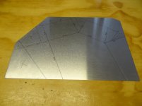
Throttle Quadrant - Part 1
Having 2 doors on the aircraft brings 2 problems. The first one is that you have to re-route the fuel lines and the second one concerns the throttle. You don’t want the throttle to get in the way (cut-off position) when trying to exit through the left door. It is already difficult enough to get out of the cub as it is. I have seen few pics of 2 door cubs with the throttle installation and that gave me couple ideas. Also, I shopped around for a throttle quadrant but they were either too big / too wide for the proposed location. Furthermore, I want the throttle to be paired with the carb heat for obvious reasons.
After considering all options, I have decided to built my own throttle. Once you understand the architecture and the movements of the levers, it is pretty straight forward. As you have seen so far in my previous posts, I like putting on paper the parts to be made. Here it is the drawing…


Took a little bit of brain juice here but it is a nice challenge to come up with a custom made throttle (read nuts!)
.JPG")
.JPG")
So, as per plan here is the plywood support and brackets for the throttle assy. The plywood received 3 coats of varnish.
.JPG")
.JPG")
.JPG")
.jpg")
For the Throttle Guide plate, it is made from a 90 degree angle bar aluminium 3/32'' thick. I made a pressing jig with a piece of 2 x 4 and using my 12 ton hydraulic jack (obviously an overkill...) and bent it into shape.
.JPG")
Here is the location for the throttle assy.
.JPG")
.JPG")
Using a dremel tool, I cut the openings for the throttle and carb heat levers. Also, inside the aluminium frame I will have a piece of teflon with guides that have smaller openings so that the levers don't rub against the aluminium.
.JPG")
.JPG")
More to follow...
Dan
Having 2 doors on the aircraft brings 2 problems. The first one is that you have to re-route the fuel lines and the second one concerns the throttle. You don’t want the throttle to get in the way (cut-off position) when trying to exit through the left door. It is already difficult enough to get out of the cub as it is. I have seen few pics of 2 door cubs with the throttle installation and that gave me couple ideas. Also, I shopped around for a throttle quadrant but they were either too big / too wide for the proposed location. Furthermore, I want the throttle to be paired with the carb heat for obvious reasons.
After considering all options, I have decided to built my own throttle. Once you understand the architecture and the movements of the levers, it is pretty straight forward. As you have seen so far in my previous posts, I like putting on paper the parts to be made. Here it is the drawing…
Took a little bit of brain juice here but it is a nice challenge to come up with a custom made throttle (read nuts!)
So, as per plan here is the plywood support and brackets for the throttle assy. The plywood received 3 coats of varnish.
For the Throttle Guide plate, it is made from a 90 degree angle bar aluminium 3/32'' thick. I made a pressing jig with a piece of 2 x 4 and using my 12 ton hydraulic jack (obviously an overkill...) and bent it into shape.
Here is the location for the throttle assy.
Using a dremel tool, I cut the openings for the throttle and carb heat levers. Also, inside the aluminium frame I will have a piece of teflon with guides that have smaller openings so that the levers don't rub against the aluminium.
More to follow...
Dan
Attachments
-
 IMG_1206.jpg96.5 KB · Views: 2,423
 -
 IMG_1207.jpg91.7 KB · Views: 2,237
 -
 002 (14).JPG160.4 KB · Views: 109
 -
 002 (13).JPG179.1 KB · Views: 112
 -
 002 (4).JPG136.8 KB · Views: 107
 -
 002 (6).JPG132.3 KB · Views: 113
 -
 002 (7).JPG127 KB · Views: 117
 -
 002 (8).jpg129.7 KB · Views: 104
 -
 002 (24).JPG136.9 KB · Views: 107
 -
 003 (2).JPG148.3 KB · Views: 112
 -
 010 (4).JPG181.5 KB · Views: 107
 -
 003 (23).JPG137.9 KB · Views: 106
 -
 003 (25).JPG117.8 KB · Views: 113
djm makes some nice quadrants https://www.flyboyaccessories.com/category-s/36.htm
Buzzcola777
MEMBER
Montreal, Canada
djm makes some nice quadrants https://www.flyboyaccessories.com/category-s/36.htm
Tempdoug,
Thanks for the post. I had seen these quadrants which are really nice but I would have to modify it for the limited space I have. Well, I'll give it a try with my custom made throttle and if it fails I'll give them a call.
Buzzcola777
MEMBER
Montreal, Canada
Throttle Quadrant – Part 2
.JPG")
Now for the throttle handle grip, I bought a pair of bicycle handles and shorten it to the right length. I made one for the pilot and also for the passenger.
.JPG")
.JPG")
Took a broomstick and sand it down to fit the opening and...
 (3).JPG")
threaded 2 holes into the throttle lever.
.JPG")
All the parts required to make this throttle quadrant are seen here. The teflon drums are 1/4'' thick and 2 1/8'' in dia. The friction tab plates are 6061 AL .050''. The throttle has a bottom hole in order to connect with the passenger's throttle.
.JPG")
.JPG")
.JPG")
.JPG")
.JPG")
.JPG")
.JPG")
.JPG")
.JPG")
.JPG")
Here is the sequence to put all pieces together. I think that by having a high contact volume with the large drums gives a very smooth and consistent travel, no sticking fore & aft. The knob regulates the right amount of pressure for the phase of flight. Really happy with the result!!
.JPG")
.JPG")
I was not satisfied with the grip on the carb heat lever. So I made a drawing and computerized it for the 3D printer.


I think it look and feels better.

As mention earlier I also made a smaller throttle version for the pax.

You can see here how the fore & aft throttles are connected. Aldo the rod is right below the door tube.
More to follow...
Dan
Now for the throttle handle grip, I bought a pair of bicycle handles and shorten it to the right length. I made one for the pilot and also for the passenger.
Took a broomstick and sand it down to fit the opening and...
threaded 2 holes into the throttle lever.
All the parts required to make this throttle quadrant are seen here. The teflon drums are 1/4'' thick and 2 1/8'' in dia. The friction tab plates are 6061 AL .050''. The throttle has a bottom hole in order to connect with the passenger's throttle.
Here is the sequence to put all pieces together. I think that by having a high contact volume with the large drums gives a very smooth and consistent travel, no sticking fore & aft. The knob regulates the right amount of pressure for the phase of flight. Really happy with the result!!
I was not satisfied with the grip on the carb heat lever. So I made a drawing and computerized it for the 3D printer.
I think it look and feels better.
As mention earlier I also made a smaller throttle version for the pax.
You can see here how the fore & aft throttles are connected. Aldo the rod is right below the door tube.
More to follow...
Dan
Attachments
-
 009 (5).JPG202.8 KB · Views: 173
 -
 009 (3).JPG217.8 KB · Views: 181
 -
 009 (6).JPG163.7 KB · Views: 125
 -
 009 (6A) (3).JPG208 KB · Views: 128
 -
 009 (6A).JPG212.1 KB · Views: 2,146
 -
 010 (7).JPG244.1 KB · Views: 114
 -
 010 (14).JPG228.6 KB · Views: 107
 -
 010 (15).JPG249.1 KB · Views: 117
 -
 010 (16).JPG251.7 KB · Views: 128
 -
 010 (17).JPG253.8 KB · Views: 121
 -
 010 (18).JPG244.4 KB · Views: 129
 -
 010 (19).JPG233.5 KB · Views: 114
 -
 010 (20).JPG227.3 KB · Views: 112
 -
 010 (21).JPG195.9 KB · Views: 109
 -
 010 (22).JPG265 KB · Views: 108
 -
 3000 (1).JPG190.7 KB · Views: 110
 -
 3000 (2).JPG154.9 KB · Views: 111
 -
 IMG_1361.jpg22.9 KB · Views: 111
 -
 IMG_1363.jpg57 KB · Views: 113
 -
 IMG_1367.jpg51.8 KB · Views: 114
 -
 IMG_1369.jpg55.5 KB · Views: 126
Buzzcola777
MEMBER
Montreal, Canada
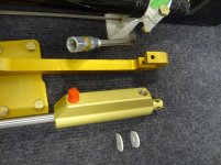
Wheels and Brakes
Finally received my wheels & brakes from MATCO. The model that I bought is WI600XLT. here is a quick description:
''MATCO mfg produces this outstanding 600X6 wheel with a triple piston I Series brake assembly. The WI600XLT-1 configuration is specifically for the PA-18 AXLE installation. This wheel and brake assembly is designed for use on high performance aircraft over 2,000 pounds that require maximum braking dynamics''
The WHLW600XLT is designed for the following standards:


On the second photo you can see the 3 pistons.
.JPG")
Here is the Brake Plate Drawing. There are about 4 differents positions that can be installed on the axle plate.
.JPG")
Holes drilled & plates installed.
.JPG")
.JPG")
Next comes the axle spacer.
.JPG")
Better view of the brake assy.
.jpg")
Fitted on the disc.
.jpg")
.JPG")
.jpg")
.JPG")

Next, brake lines installation...
Dan
Finally received my wheels & brakes from MATCO. The model that I bought is WI600XLT. here is a quick description:
''MATCO mfg produces this outstanding 600X6 wheel with a triple piston I Series brake assembly. The WI600XLT-1 configuration is specifically for the PA-18 AXLE installation. This wheel and brake assembly is designed for use on high performance aircraft over 2,000 pounds that require maximum braking dynamics''
The WHLW600XLT is designed for the following standards:
| Static Capacity | 1860 LBS |
| Load Limit | 5580 LBS |
| Maximum Accelerate/Stop Kinetic Energy | 225000 ft-lb |
| Torque Rating (@450 PSI) | 6441 in-lb |
On the second photo you can see the 3 pistons.
Here is the Brake Plate Drawing. There are about 4 differents positions that can be installed on the axle plate.
Holes drilled & plates installed.
Next comes the axle spacer.
Better view of the brake assy.
Fitted on the disc.
Next, brake lines installation...
Dan
Attachments
-
 000001.jpg121.5 KB · Views: 115
 -
 000001a.jpg108.5 KB · Views: 116
 -
 001 (01).JPG137.8 KB · Views: 102
 -
 001 (11).JPG120.1 KB · Views: 111
 -
 001 (13a).JPG102.2 KB · Views: 118
 -
 001 (15).JPG98.1 KB · Views: 105
 -
 001 (15b).JPG158.6 KB · Views: 114
 -
 001 (17).jpg88.4 KB · Views: 97
 -
 003 (20).jpg99.7 KB · Views: 119
 -
 003 (24).JPG126.1 KB · Views: 114
 -
 004 (8).jpg75.9 KB · Views: 105
 -
 005 (30).JPG135.6 KB · Views: 108
 -
 IMG_0771.jpg51.4 KB · Views: 107
Buzzcola777
MEMBER
Montreal, Canada
Looking at the 26'' / 29'' Alaskan Bushwheels. Eventhough I have seen a buch of pictures with Cubs on bushwheels, I am not too sure which size is best for the day to day flying...
[FONT="]Concerning the wheels, Alaskan Bushwheels tires fit standard 6" wheels.[/FONT]
[FONT="]Concerning the wheels, Alaskan Bushwheels tires fit standard 6" wheels.[/FONT]
Buzzcola777
MEMBER
Montreal, Canada
Braided Brake Lines installation
Finallyreceived the hardware needed to complete the brake lines installation. I just want to mention here that what you've seen so far is really aimed at beginners like myself. It is basic stuff for most of you and that is why I rely on you to notify me when something is wrong. Always ready to learn ...

Quick drawing of the hardware needed...
 (4).JPG")
.JPG")
All the material was order from Summit Racing Equipment. Good price and compatible with aviation AN.
.jpg")
.jpg")
.jpg")
.jpg")
The brakes were bought from Larry Bauer.
.jpg")
To make a straight cut, a piece of Duct Tape does the job.
.jpg")
The AN833-4D Elbow makes the connection between the fuselage and the landing gear leg.
.JPG")
Better view of boths lines installed.
.JPG")
.jpg")
.JPG")
.JPG")
Voilà !
More to follow
Dan
Finallyreceived the hardware needed to complete the brake lines installation. I just want to mention here that what you've seen so far is really aimed at beginners like myself. It is basic stuff for most of you and that is why I rely on you to notify me when something is wrong. Always ready to learn ...
Quick drawing of the hardware needed...
All the material was order from Summit Racing Equipment. Good price and compatible with aviation AN.
The brakes were bought from Larry Bauer.
To make a straight cut, a piece of Duct Tape does the job.
The AN833-4D Elbow makes the connection between the fuselage and the landing gear leg.
Better view of boths lines installed.
Voilà !
More to follow
Dan
Attachments
-
 01a.jpg83.5 KB · Views: 1,793
 -
 03 (5a) (4).JPG115.9 KB · Views: 129
 -
 03 (6).JPG107.8 KB · Views: 112
 -
 004 (2).jpg106.7 KB · Views: 114
 -
 004 (3).jpg106.4 KB · Views: 113
 -
 004 (4).jpg93.8 KB · Views: 123
 -
 004 (5).jpg123 KB · Views: 134
 -
 004 (6).jpg73.2 KB · Views: 121
 -
 004 (12a).jpg116.9 KB · Views: 114
 -
 007 (1).JPG120.5 KB · Views: 117
 -
 004 (20).JPG114.2 KB · Views: 106
 -
 004 (21a).jpg174.5 KB · Views: 114
 -
 004 (23).JPG117.3 KB · Views: 117
 -
 004 (24).JPG98.4 KB · Views: 131
skywagon8a
MEMBER
SE Mass MA6
When the brake is applied, the master cylinder moves in an arc. Is there adequate clearance between the fitting and the torque tube upright? It doesn't look like it in the picture. If there is not, over time stresses can/will break the fitting.
Buzzcola777
MEMBER
Montreal, Canada
How much play do I need to allow the master cylinder to move in an arc?
skywagon8a
MEMBER
SE Mass MA6
Just cycle the pedal full travel without fluid. Place a piece of paper in the potential interference location. Be certain you can move the paper when in the most restrictive position. Then all will be good.How much play do I need to allow the master cylinder to move in an arc?
Buzzcola777
MEMBER
Montreal, Canada
Just cycle the pedal full travel without fluid. Place a piece of paper in the potential interference location. Be certain you can move the paper when in the most restrictive position. Then all will be good.
Sky,
Thanks for your post...I'll check it out!
Dan
Buzzcola777
MEMBER
Montreal, Canada
Any progress update?
Oli, thanks for asking!
I've made a promise to my wife a long time ago that I would redo the kitchen completely. So for the last 3 months everything was thrown outside and all replace by new stuff! I will be done by Friday and I will be back in the shop with a BIG Grin on my face!!!
I see that you have a whale of a good time with your skis! That's great!! Can't wait to join you up...Probably next winter.
Take care
Dan
Similar threads
- Replies
- 20
- Views
- 2K
- Replies
- 719
- Views
- 368K
- Replies
- 22
- Views
- 12K