Fitting the windshield
Fitting Windshield
The narrow-body Super Cub comes with the two-piece aluminum windshield trim strip from Univair (
link just in case there is a need to order another one…). The wide-body comes with composite strips that I understand are much easier to install. This fact alone may push one to seriously consider the wide body! This step took me a long time. A big part of the time was learning how to stretch and shrink aluminum in a way that was acceptable to me.
I’ll outline my methods below in the hopes that they help somebody else out. I am by no means an expert here and there may be much better methods.
If you search
youtube for “backcountry supercub windshield”, you’ll hopefully find the video laying out the process for the Backcountry supercub. It’s not exactly the same, but is a good primer.
Before getting into the process, I thought I’d lay out the main tools I used:
Bending block – I copied something similar I saw in Jay’s shop. This tool was indispensable for bending the trim strips using something other than the boot cowl. I made mine by taking a belt sander to a piece of 4x4. By the way, in the picture below, you can see something of a before and after in terms of the trim strips and how they end up a little more squared through the bending process.
![IMG_3169[1].jpg](https://www.supercub.org/forum/data/attachments/50/50364-eff397fcd1272636e01a6ea3668aa0b1.jpg "IMG_3169[1].jpg")
Metal stretcher/shrinker
from Harbor Freight – I agonized over purchasing these because they cost about $150 and I can’t think of another time I’ll use them besides this time. However, since I’d never worked with tools like this before, I didn’t want to borrow them from someone and feel like I had to hurry up and use them to get them back (that being said, if anyone wants to borrow mine, you’re welcome to them!) These are pretty simple tools and might need a little grease and attention prior to their use. At one point during the project, the shrinking tool was not operating smoothly until I took it apart, cleaned it up and added some grease – then it was good to go again.
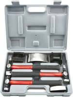
 Hammer and dolly set
 – So far, I’ve used this for a few purposes: 1) knocking down some of the ridges from the tooling above; 2) “stretching” the material when it only needed a little stretch; and 3) removing the bevel bend in the top of the front trim strip in order to put it in the stretch or shrink tool.

Inner/rear windshield strip
As I was contemplating writing this up, I was thinking of suggesting that the best approach to getting this right was to just rub your lucky rabbit’s foot and burn some sage. Then, I was heartened re-
reading Bill Rusk’s write-up on the matter:
I wish I could give really good directions for installing the inner windshield strip but this one is tough.
Here is how I ended up approaching it along with some additional hints. I don’t know that this is the best way to approach it – just how I did it.
Step 1: Using a fabric tape, locate and mark the center of each trim strip.
Step 2: Measure back 5” from the top of the firewall and make a mark on the boot cowl (equally between the two rows of rivets). The front edge of the rear trim strip will go here.
Step 3: Reference line: Mark the top middle of the windshield and the bottom of the windshield. Place the windshield on the boot cowl. Line up the top middle mark with the center Piper channel and lightly clamp the top of the windshield in place. Line up the bottom middle mark on the windshield with the mark on the boot cowl from step #2. Secure the sides of the windshield as well using clamps. Trace the bottom of the windshield onto the boot cowl. This is to provide a general idea of how the trim strip will curve around the boot cowl.
Step 4: Carefully bend the strip to match the contour of the boot cowl
This (and step 5) is the hardest part and took the longest
Use a bending block as described above and take your time. I always tried to quit for the day when I found myself getting antsy about the results.
![IMG_3331[1].jpg](https://www.supercub.org/forum/data/attachments/35/35618-80ad5a764c33e45a8a0e18a4f13cd9b4.jpg "IMG_3331[1].jpg")
Don’t kink it – it’s very easy to put too much bending pressure on the strip if you’re not paying attention and have your hands too far apart. The fix for this (for me) was to only bend when my hands were very close to each other. Once you kink the metal, it will always want to bend at that point and making further shaping very difficult. I had what I’ll call an “incipient” kink that I had to be very careful with – and which impacted how tightly I could bend the strip on the left side.
Step 5: Once you’ve got the strip pretty close to matching the shape of the boot cowl, start thinking about how you are going to get the windshield-backing part of the strip to align with the windshield. I did this by taping down the trim strip “about” where it would go and then putting the windshield on. This gave me a general idea of how the windshield would meet the trim strip.
You will likely have “pooches” where the strip is sticking up at too sharp of an angle from the boot cowl and needs to relax a bit. For me, this was in the very front and right at the sharper turns on the sides. These areas need to be “shrunk”.
The shrinker essentially grabs the aluminum and squeezes it together thereby “shrinking” the material. In the case of the trim strip, shrinking the metal -- and I only put the wide end (i.e. the backing) of the trim strip in the shrinker or stretcher – either pulls the backing back toward the cockpit or allows a sharper bend of the trim strip while keeping the backing in the same place.
Below is a couple of pictures from when I was working on the front trim strip showing the results of using the shrinker (of course the second picture looks like I'm just pressing harder, but that's honestly not the case!)
![IMG_3358[1].JPG](https://www.supercub.org/forum/data/attachments/35/35586-a5d07c342f8c9d0ad3c4c0a243d5359b.jpg "IMG_3358[1].JPG")
![IMG_3359[1].JPG](https://www.supercub.org/forum/data/attachments/35/35592-7078dce67b02d602e58492900e735785.jpg "IMG_3359[1].JPG")
I made a bunch of test strips to get a feel for how much pressure to use on the tool and what results I got.
![IMG_3364[1].JPG](https://www.supercub.org/forum/data/attachments/35/35598-02a430d4a4fe0afb6ba99bc823a0b79f.jpg "IMG_3364[1].JPG")
There is a limit to how much aluminum can be worked and I tried not to find that limit.
Step 6: Drill holes
First, try to wait as long as possible to drill holes in the strip – there are a few reasons for this. First, as Jay taught me with the fuel lines during the builder’s assist week, it’s a good idea to work the part until its “happy” in its position. In other words, better not have it in place under stress. Second, you can crack the metal at the holes if you continue to work it significantly after the holes were drilled. Finally, after the 3[SUP]rd[/SUP] or 4[SUP]th[/SUP] time you re-cleco the piece onto the cowl, you will begin to experience loose clecos which result from the #40 holes beginning to wallow out. Not only do these clecos not do their job, you may be forced to move to a larger rivet (not the end of the world, but seems like it should be avoided).
The inner strip has a hole in the center and then additional holes every 2”. Using a #40 bit, drill and cleco the center hole and then proceed outward from the center. After I had a few holes on either side, I paused the drilling, took the strip off, and made bending adjustments before continuing to drill. Here's a picture of the inner strip clecoed in place with the windshield.
![IMG_3321[1].jpg](https://www.supercub.org/forum/data/attachments/35/35602-b74ba1d96aff0b6ecfa18ca8c6c07cb4.jpg "IMG_3321[1].jpg")
Also, don’t rush replacing the trim strip after you’ve made some shrinking or other adjustments. Take the time to make sure it is re-bent to fit nicely. Otherwise, you’ll be putting unnecessary stress on the clecos. Also, pay attention to a few-hole’s-distance beyond the hole you’re currently drilling to make sure you’re headed in the right direction before securing the strip.
You will also need to “flatten” the trim strip where the side of the boot cowl is essentially vertical at the end. Also, you may need to put a little more bend into the instrument panel as it may stick out a bit too much where the rear trim strip passes it. Finally, the backcountry video has a pretty good description of where the trim strip should end up (in terms of up and down location). For length, I cut it short of the “fuselage side” (not sure the name) so that the windshield could lie flush on the inner trim strip and the fuselage side (i.e. on the same plane)
Step 7: Final adjustment and riveting
Once you have the holes drilled and the strip clecoed in place, put the windshield on and check for proper fit with the trim strip. If there are gaps, those areas need to be stretched. If there are “pooches”, those areas need to be shrunk.
When you’re happy with the fit, remove the strip and countersink the holes for rivets. (Technically, I think the material thickness calls for dimpling, but I went with counter-sinking and like the results). The rivets you will be placing are temporary and you’ll be drilling them out. As such, use aluminum rivets. I was able to find 3/32” aluminum flush pop rivets from
McMaster Carr.
For riveting, like the clecos, start from the middle and work your way out. I drafted my son to crawl into the cockpit and place opposing pressure from the inside of the boot cowl so that I could put some good pressure on the rivet and avoid any gaps in the riveting and get a nice tight fit.
![IMG_3327[1].JPG](https://www.supercub.org/forum/data/attachments/35/35610-72cb9cf6876b8743912bb16e4fbb07eb.jpg "IMG_3327[1].JPG")
Step 8: Place the windshield on and use a ratchet strap (attached to the strut fitting points). The picture in step 6 above shows the ratchet strap in place. Somewhere along the way, I drilled the top of the windshield to be able to secure it. But I left drilling the sides until the end. Also, I trimmed a little bit of the bottom of the windshield in a couple of places where it was hanging too low on the inner trim strip. I used a Dremel and made multiple passes with pauses in between so that the plastic never got too hot. Also, I ended up putting on and taking off the windshield a number of times and adjusting the inner trim strip until I has happy with the fit (I should say “happier” because as I write this, I am still considering one more stretch of the inner strip after I remove the temporary clecos.
Step 9: Fit the front windshield strip. This is a little easier this time around because the rear strip and windshield is already on – so you’re not guessing as much about fit. Essentially, repeat steps 4-6 with the front trim strip. (As you get to about where the final holes would be, go to step 10).
You’ll notice that the front trim strip has a slight bevel bend at the top. You’ll need to remove this in order to use the stretcher/shrinkers. I used the hammer and dolly for this.
The holes will begin one inch out from the center and proceed every two inches (so that each hole is between the holes in the inner strip). I just measured the center point between each inner strip rivet and drew a line outward. Then, I put on the outer strip and transferred the lines onto the strip to know where to drill.
![IMG_3361[1].JPG](https://www.supercub.org/forum/data/attachments/35/35625-be4513fe3cded93f5103dc8bdf540798.jpg "IMG_3361[1].JPG")
Step 10: Side trim pieces. The side trim pieces are secured with five screws. In order to give some room on the backside next to the tube, I placed the holes 7/16” from the edge of the trim strip (and underlying fuselage). I put the first hole about an inch down from the top. The bottom home, if all goes well, will marry: the outer strip, the side trim strip, the windshield, and the fuselage side (see picture below). After these two, I placed another three screws equally placed down the trim strip.

![IMG_2747[1].JPG](https://www.supercub.org/forum/data/attachments/33/33694-b8bf9e2bbceb96f2f265fc8200446862.jpg "IMG_2747[1].JPG")
![IMG_2540[1].JPG](https://www.supercub.org/forum/data/attachments/33/33700-05859dc5da8f440f640b3877b06cfa96.jpg "IMG_2540[1].JPG")

![IMG_2704[1].jpg](https://www.supercub.org/forum/data/attachments/33/33705-9acc0f7f69ece59b2fd75ad5de4a37d0.jpg "IMG_2704[1].jpg")
![IMG_2703[1].jpg](https://www.supercub.org/forum/data/attachments/33/33711-9de5ee64f41d12275c35000ce201cdcb.jpg "IMG_2703[1].jpg")
![IMG_2694[1].jpg](https://www.supercub.org/forum/data/attachments/33/33714-13a257966bf6b121bee33db34a442b43.jpg "IMG_2694[1].jpg")
![IMG_2882[1].jpg](https://www.supercub.org/forum/data/attachments/33/33719-fbe04f2fec1465faff8d45cb73f2cb18.jpg "IMG_2882[1].jpg")
![IMG_3349[1].jpg](https://www.supercub.org/forum/data/attachments/33/33725-fb86d45636bea4011ee3877896e31f5b.jpg "IMG_3349[1].jpg")
![IMG_3350[1].jpg](https://www.supercub.org/forum/data/attachments/33/33732-9837ee706c5f0fc0fd08446e1e991350.jpg "IMG_3350[1].jpg")
![IMG_3353[1].jpg](https://www.supercub.org/forum/data/attachments/33/33738-57a06547746e06ade19e87ab7b85e605.jpg "IMG_3353[1].jpg")
![IMG_2747[1].JPG](/forum/data/attachments/33/33694-b8bf9e2bbceb96f2f265fc8200446862.jpg)
![IMG_2540[1].JPG](/forum/data/attachments/33/33700-05859dc5da8f440f640b3877b06cfa96.jpg)
![IMG_2704[1].jpg](/forum/data/attachments/33/33705-9acc0f7f69ece59b2fd75ad5de4a37d0.jpg)
![IMG_2703[1].jpg](/forum/data/attachments/33/33711-9de5ee64f41d12275c35000ce201cdcb.jpg)
![IMG_2694[1].jpg](/forum/data/attachments/33/33714-13a257966bf6b121bee33db34a442b43.jpg)
![IMG_2882[1].jpg](/forum/data/attachments/33/33719-fbe04f2fec1465faff8d45cb73f2cb18.jpg)
![IMG_3349[1].jpg](/forum/data/attachments/33/33725-fb86d45636bea4011ee3877896e31f5b.jpg)
![IMG_3350[1].jpg](/forum/data/attachments/33/33732-9837ee706c5f0fc0fd08446e1e991350.jpg)
![IMG_3353[1].jpg](/forum/data/attachments/33/33738-57a06547746e06ade19e87ab7b85e605.jpg)
![IMG_3169[1].jpg](/forum/data/attachments/50/50364-eff397fcd1272636e01a6ea3668aa0b1.jpg)

![IMG_3358[1].JPG](/forum/data/attachments/35/35586-a5d07c342f8c9d0ad3c4c0a243d5359b.jpg)
![IMG_3359[1].JPG](/forum/data/attachments/35/35592-7078dce67b02d602e58492900e735785.jpg)
![IMG_3364[1].JPG](/forum/data/attachments/35/35598-02a430d4a4fe0afb6ba99bc823a0b79f.jpg)
![IMG_3321[1].jpg](/forum/data/attachments/35/35602-b74ba1d96aff0b6ecfa18ca8c6c07cb4.jpg)
![IMG_3327[1].JPG](/forum/data/attachments/35/35610-72cb9cf6876b8743912bb16e4fbb07eb.jpg)
![IMG_3331[1].jpg](/forum/data/attachments/35/35618-80ad5a764c33e45a8a0e18a4f13cd9b4.jpg)
![IMG_3361[1].JPG](/forum/data/attachments/35/35625-be4513fe3cded93f5103dc8bdf540798.jpg)

![IMG_3388[1].jpg](https://www.supercub.org/forum/data/attachments/52/52714-4db98b25d0f225f9f40b2709d549b25a.jpg "IMG_3388[1].jpg")
![IMG_3370[1].jpg](https://www.supercub.org/forum/data/attachments/52/52719-48586cc559acebfeaa49dc287b13c3eb.jpg "IMG_3370[1].jpg")
![IMG_3371[1].jpg](https://www.supercub.org/forum/data/attachments/52/52724-369d0a66d0fad58cc75f9df3bcf611af.jpg "IMG_3371[1].jpg")
![IMG_3383[1].jpg](https://www.supercub.org/forum/data/attachments/52/52729-af44091315af72d2b9ad5191eedbfd98.jpg "IMG_3383[1].jpg")
![IMG_3373[1].JPG](https://www.supercub.org/forum/data/attachments/34/34442-0f3df4dae65f5beca2f33d2506f7ae8e.jpg "IMG_3373[1].JPG")
![IMG_3509[1].jpg](https://www.supercub.org/forum/data/attachments/34/34450-899b288890123716cf421dcb02c21691.jpg "IMG_3509[1].jpg")
![IMG_3403[1].jpg](https://www.supercub.org/forum/data/attachments/34/34457-dd7fa764a18b48a449214aed3d91ebb4.jpg "IMG_3403[1].jpg")
![IMG_3402[1].jpg](https://www.supercub.org/forum/data/attachments/34/34464-19239a6bf9b3cfbb96dd6e5a35340e29.jpg "IMG_3402[1].jpg")
![IMG_3404[1].jpg](https://www.supercub.org/forum/data/attachments/34/34469-783d56b000194f1997f02acd3edc8e92.jpg "IMG_3404[1].jpg")
![IMG_3401[1].jpg](https://www.supercub.org/forum/data/attachments/34/34473-b4f0dcdcef670989f43455e4d4c59915.jpg "IMG_3401[1].jpg")
![IMG_3400[1].jpg](https://www.supercub.org/forum/data/attachments/34/34479-c7e784458d4f61eac360f7383147df83.jpg "IMG_3400[1].jpg")
![IMG_3466[1].jpg](https://www.supercub.org/forum/data/attachments/34/34486-f793bb34a0f3538c33c9431304e54ac8.jpg "IMG_3466[1].jpg")
![JWXY0291[1].jpg](https://www.supercub.org/forum/data/attachments/34/34493-83bd3edd1db3fb997fea154a6f28d81c.jpg "JWXY0291[1].jpg")
![GUGI1753[1].jpg](https://www.supercub.org/forum/data/attachments/34/34498-3412f7528d43bf6a567b61df2458fb23.jpg "GUGI1753[1].jpg")
![IMG_3458[1].jpg](https://www.supercub.org/forum/data/attachments/34/34505-18d2dee9a59482a87f3fa9aa6b3a9666.jpg "IMG_3458[1].jpg")
![IMG_3506[1].jpg](https://www.supercub.org/forum/data/attachments/34/34508-db117c48e1553ea8253981c10ff6bc4e.jpg "IMG_3506[1].jpg")
![IMG_3507[1].jpg](https://www.supercub.org/forum/data/attachments/34/34514-61f1aeb71476737240aad2b387c76011.jpg "IMG_3507[1].jpg")
![IMG_3503[1].jpg](https://www.supercub.org/forum/data/attachments/34/34523-7497b3ad9416588f51d594e88818a611.jpg "IMG_3503[1].jpg")
![IMG_3388[1].jpg](/forum/data/attachments/52/52714-4db98b25d0f225f9f40b2709d549b25a.jpg)
![IMG_3370[1].jpg](/forum/data/attachments/52/52719-48586cc559acebfeaa49dc287b13c3eb.jpg)
![IMG_3371[1].jpg](/forum/data/attachments/52/52724-369d0a66d0fad58cc75f9df3bcf611af.jpg)
![IMG_3383[1].jpg](/forum/data/attachments/52/52729-af44091315af72d2b9ad5191eedbfd98.jpg)
![IMG_3373[1].JPG](/forum/data/attachments/34/34442-0f3df4dae65f5beca2f33d2506f7ae8e.jpg)
![IMG_3509[1].jpg](/forum/data/attachments/34/34450-899b288890123716cf421dcb02c21691.jpg)
![IMG_3403[1].jpg](/forum/data/attachments/34/34457-dd7fa764a18b48a449214aed3d91ebb4.jpg)
![IMG_3402[1].jpg](/forum/data/attachments/34/34464-19239a6bf9b3cfbb96dd6e5a35340e29.jpg)
![IMG_3404[1].jpg](/forum/data/attachments/34/34469-783d56b000194f1997f02acd3edc8e92.jpg)
![IMG_3401[1].jpg](/forum/data/attachments/34/34473-b4f0dcdcef670989f43455e4d4c59915.jpg)
![IMG_3400[1].jpg](/forum/data/attachments/34/34479-c7e784458d4f61eac360f7383147df83.jpg)
![IMG_3466[1].jpg](/forum/data/attachments/34/34486-f793bb34a0f3538c33c9431304e54ac8.jpg)
![JWXY0291[1].jpg](/forum/data/attachments/34/34493-83bd3edd1db3fb997fea154a6f28d81c.jpg)
![GUGI1753[1].jpg](/forum/data/attachments/34/34498-3412f7528d43bf6a567b61df2458fb23.jpg)
![IMG_3458[1].jpg](/forum/data/attachments/34/34505-18d2dee9a59482a87f3fa9aa6b3a9666.jpg)
![IMG_3506[1].jpg](/forum/data/attachments/34/34508-db117c48e1553ea8253981c10ff6bc4e.jpg)
![IMG_3507[1].jpg](/forum/data/attachments/34/34514-61f1aeb71476737240aad2b387c76011.jpg)
![IMG_3503[1].jpg](/forum/data/attachments/34/34523-7497b3ad9416588f51d594e88818a611.jpg)
![HAWU2173[1].JPG](https://www.supercub.org/forum/data/attachments/42/42611-8680c15a8678c395cc667bbc43cc5f0b.jpg "HAWU2173[1].JPG")
![IMG_3475[1].jpg](https://www.supercub.org/forum/data/attachments/42/42613-4e231164e6770f31a7eeab7ef6b22a17.jpg "IMG_3475[1].jpg")
![IMG_3476[1].jpg](https://www.supercub.org/forum/data/attachments/42/42622-34045f754884f0c76689e38b02be706e.jpg "IMG_3476[1].jpg")
![IMG_3481[1].jpg](https://www.supercub.org/forum/data/attachments/42/42627-b9579715e1bb6628f62c699546ef85bb.jpg "IMG_3481[1].jpg")
![IMG_3660[1].JPG](https://www.supercub.org/forum/data/attachments/42/42631-0f1892b7be769b5b9b0fd8ce06ce7207.jpg "IMG_3660[1].JPG")
![IMG_3666[1].JPG](https://www.supercub.org/forum/data/attachments/42/42635-acc0fddcffadc7a0e51b606320c878fe.jpg "IMG_3666[1].JPG")
![IMG_3482[1].jpg](https://www.supercub.org/forum/data/attachments/42/42640-7a9325172b1f8ce0725e7593e167bea5.jpg "IMG_3482[1].jpg")
![IMG_3483[1].jpg](https://www.supercub.org/forum/data/attachments/42/42645-12c0f16e46f996242bad267af2a1f00f.jpg "IMG_3483[1].jpg")
![IMG_3491[1].JPG](https://www.supercub.org/forum/data/attachments/42/42653-f857260cdccc093fa2c0fdc97e89d6d4.jpg "IMG_3491[1].JPG")
![IMG_3670[1].JPG](https://www.supercub.org/forum/data/attachments/42/42658-7f478b16df7ba63f22500b3b17763933.jpg "IMG_3670[1].JPG")
![IMG_3671[1].JPG](https://www.supercub.org/forum/data/attachments/42/42663-406243df983ca10a2f71a80add6b1e71.jpg "IMG_3671[1].JPG")
![IMG_3672[1].JPG](https://www.supercub.org/forum/data/attachments/42/42667-66f8f940c842ac13d010554d4922c945.jpg "IMG_3672[1].JPG")
![IMG_3785[1].jpg](https://www.supercub.org/forum/data/attachments/42/42693-7f8778da2ad8908dd88cca3c37a07031.jpg "IMG_3785[1].jpg")
![IMG_3786[1].JPG](https://www.supercub.org/forum/data/attachments/42/42695-7c1c18636d13b7369d61d7241bd61266.jpg "IMG_3786[1].JPG")
![HAWU2173[1].JPG](/forum/data/attachments/42/42611-8680c15a8678c395cc667bbc43cc5f0b.jpg)
![IMG_3475[1].jpg](/forum/data/attachments/42/42613-4e231164e6770f31a7eeab7ef6b22a17.jpg)
![IMG_3476[1].jpg](/forum/data/attachments/42/42622-34045f754884f0c76689e38b02be706e.jpg)
![IMG_3481[1].jpg](/forum/data/attachments/42/42627-b9579715e1bb6628f62c699546ef85bb.jpg)
![IMG_3660[1].JPG](/forum/data/attachments/42/42631-0f1892b7be769b5b9b0fd8ce06ce7207.jpg)
![IMG_3666[1].JPG](/forum/data/attachments/42/42635-acc0fddcffadc7a0e51b606320c878fe.jpg)
![IMG_3482[1].jpg](/forum/data/attachments/42/42640-7a9325172b1f8ce0725e7593e167bea5.jpg)
![IMG_3483[1].jpg](/forum/data/attachments/42/42645-12c0f16e46f996242bad267af2a1f00f.jpg)
![IMG_3491[1].JPG](/forum/data/attachments/42/42653-f857260cdccc093fa2c0fdc97e89d6d4.jpg)
![IMG_3670[1].JPG](/forum/data/attachments/42/42658-7f478b16df7ba63f22500b3b17763933.jpg)
![IMG_3671[1].JPG](/forum/data/attachments/42/42663-406243df983ca10a2f71a80add6b1e71.jpg)
![IMG_3672[1].JPG](/forum/data/attachments/42/42667-66f8f940c842ac13d010554d4922c945.jpg)
![IMG_3785[1].jpg](/forum/data/attachments/42/42693-7f8778da2ad8908dd88cca3c37a07031.jpg)
![IMG_3786[1].JPG](/forum/data/attachments/42/42695-7c1c18636d13b7369d61d7241bd61266.jpg)
![IMG_3837[1].jpg](https://www.supercub.org/forum/data/attachments/43/43097-76a9c705b35b255bd1f4c3561e6e1b3f.jpg "IMG_3837[1].jpg")
![IMG_3729[1].jpg](https://www.supercub.org/forum/data/attachments/43/43103-b0e43ad85af4a331005c0215b296ed9a.jpg "IMG_3729[1].jpg")
") )
)![IMG_3730[1].jpg](https://www.supercub.org/forum/data/attachments/43/43110-f7f0678fd59e6b41f6b8f94a601b52e7.jpg "IMG_3730[1].jpg")
![IMG_3732[1].jpg](https://www.supercub.org/forum/data/attachments/43/43116-fb4790458390fb72deeebbcfa62520ac.jpg "IMG_3732[1].jpg")
![IMG_3849[1].jpg](https://www.supercub.org/forum/data/attachments/46/46449-a26d105c9e7d3b5707f5620b781d2675.jpg "IMG_3849[1].jpg")
![IMG_3882[1].jpg](https://www.supercub.org/forum/data/attachments/46/46458-99841cd05651c3ff49b1853ecbcc9492.jpg "IMG_3882[1].jpg")
![IMG_3881[1].jpg](https://www.supercub.org/forum/data/attachments/46/46463-d5b761de9550e4918f956c8f13943340.jpg "IMG_3881[1].jpg")
![IMG_3889[1].jpg](https://www.supercub.org/forum/data/attachments/47/47860-bf563e31dbca71d779388021980e0d54.jpg "IMG_3889[1].jpg")
![IMG_3865[1].jpg](https://www.supercub.org/forum/data/attachments/47/47865-ef7ccc25c51ae67a13152a253334ddb2.jpg "IMG_3865[1].jpg")
![IMG_3869[1].jpg](https://www.supercub.org/forum/data/attachments/47/47872-6e5cbd3b80e1b97b7dd6a2b7b6591009.jpg "IMG_3869[1].jpg")
![IMG_3877[1].JPG](https://www.supercub.org/forum/data/attachments/47/47877-cb334c447cb8879d069b6d12a86862a7.jpg "IMG_3877[1].JPG")
![IMG_3885[1].jpg](https://www.supercub.org/forum/data/attachments/47/47881-76cac3a2283673b0d1de36c99ac083eb.jpg "IMG_3885[1].jpg")
![FREL1135[1].jpg](https://www.supercub.org/forum/data/attachments/47/47891-fabc19cbceae9a4298777fc9acd6c387.jpg "FREL1135[1].jpg")
![IMG_3893[1].jpg](https://www.supercub.org/forum/data/attachments/47/47905-36a9b6b75862ff738f3df7bd9dcd39e8.jpg "IMG_3893[1].jpg")
![IMG_3895[1].jpg](https://www.supercub.org/forum/data/attachments/47/47913-9eee1d74e85560e2395a1d854cdde097.jpg "IMG_3895[1].jpg")
![IMG_3897[1].jpg](https://www.supercub.org/forum/data/attachments/47/47918-3c2f51f3efd210211a97d4bcbead5f15.jpg "IMG_3897[1].jpg")
![IMG_3898[1].jpg](https://www.supercub.org/forum/data/attachments/47/47924-2ed2efad048d27d756ba93d2fb1e9f4c.jpg "IMG_3898[1].jpg")
![IMG_3900[1].JPG](https://www.supercub.org/forum/data/attachments/47/47930-011bb18d148f9752f58e627355cc98b2.jpg "IMG_3900[1].JPG")
![IMG_3917[1].jpg](https://www.supercub.org/forum/data/attachments/47/47936-332e9e83cc2bb18e34c8a08a7664d8cf.jpg "IMG_3917[1].jpg")
![IMG_3894[1].JPG](https://www.supercub.org/forum/data/attachments/47/47897-b88e54483d37edafab8d51f7dc7b0c22.jpg "IMG_3894[1].JPG")
![IMG_3921[1].jpg](https://www.supercub.org/forum/data/attachments/47/47943-1472e5150ec7923184d9187eefff6df9.jpg "IMG_3921[1].jpg")
![IMG_3927[1].jpg](https://www.supercub.org/forum/data/attachments/47/47952-8f7fa773860508411cf25d1463d3d066.jpg "IMG_3927[1].jpg")
![IMG_3926[1].JPG](https://www.supercub.org/forum/data/attachments/47/47959-10b322699ed47af327cc9553d8909259.jpg "IMG_3926[1].JPG")
![GKII0578[1].jpg](https://www.supercub.org/forum/data/attachments/47/47967-16e3d158028ec9127506022505597849.jpg "GKII0578[1].jpg")
![IMG_3889[1].jpg](/forum/data/attachments/47/47860-bf563e31dbca71d779388021980e0d54.jpg)
![IMG_3865[1].jpg](/forum/data/attachments/47/47865-ef7ccc25c51ae67a13152a253334ddb2.jpg)
![IMG_3869[1].jpg](/forum/data/attachments/47/47872-6e5cbd3b80e1b97b7dd6a2b7b6591009.jpg)
![IMG_3877[1].JPG](/forum/data/attachments/47/47877-cb334c447cb8879d069b6d12a86862a7.jpg)
![IMG_3885[1].jpg](/forum/data/attachments/47/47881-76cac3a2283673b0d1de36c99ac083eb.jpg)
![FREL1135[1].jpg](/forum/data/attachments/47/47891-fabc19cbceae9a4298777fc9acd6c387.jpg)
![IMG_3894[1].JPG](/forum/data/attachments/47/47897-b88e54483d37edafab8d51f7dc7b0c22.jpg)
![IMG_3893[1].jpg](/forum/data/attachments/47/47905-36a9b6b75862ff738f3df7bd9dcd39e8.jpg)
![IMG_3895[1].jpg](/forum/data/attachments/47/47913-9eee1d74e85560e2395a1d854cdde097.jpg)
![IMG_3897[1].jpg](/forum/data/attachments/47/47918-3c2f51f3efd210211a97d4bcbead5f15.jpg)
![IMG_3898[1].jpg](/forum/data/attachments/47/47924-2ed2efad048d27d756ba93d2fb1e9f4c.jpg)
![IMG_3900[1].JPG](/forum/data/attachments/47/47930-011bb18d148f9752f58e627355cc98b2.jpg)
![IMG_3917[1].jpg](/forum/data/attachments/47/47936-332e9e83cc2bb18e34c8a08a7664d8cf.jpg)
![IMG_3921[1].jpg](/forum/data/attachments/47/47943-1472e5150ec7923184d9187eefff6df9.jpg)
![IMG_3927[1].jpg](/forum/data/attachments/47/47952-8f7fa773860508411cf25d1463d3d066.jpg)
![IMG_3926[1].JPG](/forum/data/attachments/47/47959-10b322699ed47af327cc9553d8909259.jpg)
![GKII0578[1].jpg](/forum/data/attachments/47/47967-16e3d158028ec9127506022505597849.jpg)
![IMG_3957[1].jpg](https://www.supercub.org/forum/data/attachments/49/49289-3c1c1ac531063995d290b803111cce03.jpg "IMG_3957[1].jpg")
![IMG_3958[1].jpg](https://www.supercub.org/forum/data/attachments/49/49280-27b545231a7681bd9842eb5f41c58e92.jpg "IMG_3958[1].jpg")
![IMG_3962[1].JPG](https://www.supercub.org/forum/data/attachments/49/49286-e7210d382d2543e3cf78973f251651ed.jpg "IMG_3962[1].JPG")
![IMG_3963[1].JPG](https://www.supercub.org/forum/data/attachments/49/49295-edb26e688424aed528bee9f7de85e957.jpg "IMG_3963[1].JPG")
![IMG_3965[1].JPG](https://www.supercub.org/forum/data/attachments/49/49302-41da727e9e271fee96b07d844d046a77.jpg "IMG_3965[1].JPG")
![IMG_3966[1].JPG](https://www.supercub.org/forum/data/attachments/49/49306-682640832162e877f4e5f488d2ac363a.jpg "IMG_3966[1].JPG")

![IMG_3978[1].jpg](https://www.supercub.org/forum/data/attachments/50/50199-145933fd8602d82b9f48063f70f609c3.jpg "IMG_3978[1].jpg")

![IMG_3837[1].jpg](/forum/data/attachments/43/43097-76a9c705b35b255bd1f4c3561e6e1b3f.jpg)
![IMG_3729[1].jpg](/forum/data/attachments/43/43103-b0e43ad85af4a331005c0215b296ed9a.jpg)
![IMG_3730[1].jpg](/forum/data/attachments/43/43110-f7f0678fd59e6b41f6b8f94a601b52e7.jpg)
![IMG_3732[1].jpg](/forum/data/attachments/43/43116-fb4790458390fb72deeebbcfa62520ac.jpg)
![IMG_3849[1].jpg](/forum/data/attachments/46/46449-a26d105c9e7d3b5707f5620b781d2675.jpg)
![IMG_3882[1].jpg](/forum/data/attachments/46/46458-99841cd05651c3ff49b1853ecbcc9492.jpg)
![IMG_3881[1].jpg](/forum/data/attachments/46/46463-d5b761de9550e4918f956c8f13943340.jpg)
![IMG_3958[1].jpg](/forum/data/attachments/49/49280-27b545231a7681bd9842eb5f41c58e92.jpg)
![IMG_3962[1].JPG](/forum/data/attachments/49/49286-e7210d382d2543e3cf78973f251651ed.jpg)
![IMG_3957[1].jpg](/forum/data/attachments/49/49289-3c1c1ac531063995d290b803111cce03.jpg)
![IMG_3963[1].JPG](/forum/data/attachments/49/49295-edb26e688424aed528bee9f7de85e957.jpg)
![IMG_3965[1].JPG](/forum/data/attachments/49/49302-41da727e9e271fee96b07d844d046a77.jpg)
![IMG_3966[1].JPG](/forum/data/attachments/49/49306-682640832162e877f4e5f488d2ac363a.jpg)

![IMG_3978[1].jpg](/forum/data/attachments/50/50199-145933fd8602d82b9f48063f70f609c3.jpg)