• If You Are Having Trouble Logging In with Your Old Username and Password, Please use this Forgot Your Password link to get re-established.
  • Hey! Be sure to login or register!

And so it begins

As far as hitting your head, yes that could be an issue but we should all be wearing a helmet so we have mitigation of the issue. Form should follow function what ever it takes to do the job right.
DENNY
Denny, Wearing a helmet is something which I've heard about a fair amount here and apparently it is done quite often in Alaska. I should tell you that in all my years aviating in the lower 48, I've only seen helmets on crop duster pilots. It just isn't something pilots wear. Sure maybe leather helmets on open cockpit types, but not hard hats. If there are any they are rare.
 
Ya, I have started wearing one, not so much for landing but for in flight turbulence, I do have neck issues so I had to go for as light as possible. I would consider doing an overhead flap handle on new build but it has to work as good or better than a stock one for me to consider it.
DENNY
 
  • Like
Reactions: DCT
I’ve got a short torso and a growing midsection. The overhead flap handle is ideal for me. It’s always within the field of vision and no contortions needed away from piloting.


Sent from my iPhone using SuperCub.Org
 
I’ve got a short torso and a growing midsection. The overhead flap handle is ideal for me. It’s always within the field of vision and no contortions needed away from piloting.
I sure hope you don't repeat your last Cub's last flight. That high handle might get in the way.
 
Been working on interior panels for a few days. All panels are now fit initially. Most need to be finish trimmed. Now working on placing nut plates to anchor areas that need additional support so they don’t drum against the tubing. D window channels are not installed yet so the side panels don’t have window cut outs yet.8C0C7F2F-C3F3-44D4-A7BE-B1E6D162D745.jpgA941D5CA-10AE-4885-B557-EF52C1E9C2B6.jpeg183EA820-13B5-4377-88EC-E7079CCFDB4B.jpg
The small soffit at the bottom of the sidewall panels is where the rudder cables live.
 

Attachments

  • 8C0C7F2F-C3F3-44D4-A7BE-B1E6D162D745.jpg
    8C0C7F2F-C3F3-44D4-A7BE-B1E6D162D745.jpg
    30.7 KB · Views: 466
  • A941D5CA-10AE-4885-B557-EF52C1E9C2B6.jpeg
    A941D5CA-10AE-4885-B557-EF52C1E9C2B6.jpeg
    103.7 KB · Views: 477
  • 183EA820-13B5-4377-88EC-E7079CCFDB4B.jpg
    183EA820-13B5-4377-88EC-E7079CCFDB4B.jpg
    87 KB · Views: 494
441046E0-9B00-4EF4-AA9B-73C8E59DAA44.jpg25696EFD-8A6F-4CD8-A159-5196287CDF59.jpg
working on the cargo door. It hinges at the top, lock in the lower right corner. It will have a latching handle roughly centered in the door. Four latching pins to hold it in place, one on each side and two in the bottom. There will also be a latch handle inside.
 

Attachments

  • 441046E0-9B00-4EF4-AA9B-73C8E59DAA44.jpg
    441046E0-9B00-4EF4-AA9B-73C8E59DAA44.jpg
    67.5 KB · Views: 224
  • 25696EFD-8A6F-4CD8-A159-5196287CDF59.jpg
    25696EFD-8A6F-4CD8-A159-5196287CDF59.jpg
    70.2 KB · Views: 241
I’ve been putting off dealing with this problem for many months but now it’s time. When I tacked the aft gear/strut attach points to the fuselage I had everything clamped and held in place at a 22.5 degree angle. I removed the clamps to access all the areas needing to be welded, checked the angle again and it was spot on. At this point they are 80% welded but they have pulled off the specified angle. One is now at 22* the other at 21.5*. There is no tolerance given on figure 12. It shows 22* 30’.

Considering strut length, that change in angle would result in misalignment of roughly .3” and .6” respectively at the upper end of the struts.

I want to fix it but it’s going to be a major pain in the butt. Is there a tolerance listed that I haven’t seen? Would leaving it the way it is put stress on the strut fork?

Educated guidance would be appreciated.

Mr. Ed
 
Big ass crescent wrench is the normal fix. They get bent when struts bend from wind, snow loads, or flipping over.

Finish welding them before adjusting them to proper angle.


Sent from my iPhone using SuperCub.Org
 
Thanks Mike. I assume the big ass crescent wrench is accompanied by a prodigious amount of heat?
 
8A70B760-9D4B-436C-BB6D-E6CC87E66D0D.jpg
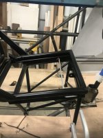
Back to work on the project after a two month break. Still waiting on some 4130 plate to finish off the Cabane V but it’s mostly done. I finished welding on all the gear attachments and couldn’t resist hanging the gear. It made a minor task feel like major progress.
 

Attachments

  • 8A70B760-9D4B-436C-BB6D-E6CC87E66D0D.jpg
    8A70B760-9D4B-436C-BB6D-E6CC87E66D0D.jpg
    65.1 KB · Views: 226
I Cub windshield can be out in 30 minutes or less. 5 or 6 screws across the skylight and down each side and it slide out of the boot cowl wrap around fairing. Don't do it often but is pretty simple and quick to do.

I leave the factory fresh air vent in the top of the boot cowl. Most people remove these at rebuild but I live in Texas where it gets hotter than I like and it is something I use a lot. It would dump a lot of air on those avionics.

Ever have trouble with it leaking? I sealed mine up permanently as it cost me a radio....rain water leaked down into the radio tray.
 
Torque tube mast modification question:

Piper drawings show a measurement of 4 11/16” from the center of the torque tube to the center of the pivot hole in the mast for the control stick. Some folks advocate shortening the mast, changing the measurement to 3 5/8” and shortening the stick stub accordingly. I understand what this accomplishes. What I would like is information from people who have made this modification and what you think. Glad you did it. Changed back to original? Since the aft stick has clearance issues with the front seat seat back and doing this modification increases the required stick travel, a modified aft mast would exacerbate that problem. So, would you recommend only modifying the front mast? Or, modify both masts and shorten the aft stick?

Any real world experience would be appreciated.

Thanks,

Mr. Ed
 
I’ve been making some progress. Torque tube, stick stubs and interconnect are installed. Aileron stops are built but not welded in place yet. Metal aft belly fabricated and installed today.

E6794050-B14B-4C28-A4B0-9EF81AC373E8.jpg
BEA7B0A6-B6D3-4721-81B7-A8F9EEFD0CB4.jpg

97D0758E-92C2-4D6A-8B7B-F3FC90EB95A9.jpg
 

Attachments

  • E6794050-B14B-4C28-A4B0-9EF81AC373E8.jpg
    E6794050-B14B-4C28-A4B0-9EF81AC373E8.jpg
    144.2 KB · Views: 197
  • BEA7B0A6-B6D3-4721-81B7-A8F9EEFD0CB4.jpg
    BEA7B0A6-B6D3-4721-81B7-A8F9EEFD0CB4.jpg
    65.1 KB · Views: 215
  • 97D0758E-92C2-4D6A-8B7B-F3FC90EB95A9.jpg
    97D0758E-92C2-4D6A-8B7B-F3FC90EB95A9.jpg
    104.4 KB · Views: 219
I’m trying to get my aileron pulley housing welded in and am missing information. The fuselage drawing shows “aileron pulley housing installation - 20272”. Northland search comes up with nothing. Christian’s site comes up empty too. I haven’t found a section drawing or figure showing it either. This is the pulley bracket that’s installed inboard of the lift strut/rear gear attach point that guides the cable from the horn on the torque tube out of the fuselage and up the back side of the forward lift strut.

Maybe it’s #’ed incorrectly on the drawing. If anybody has a drawing or guidance it would be appreciated.

Thanks
 
47D4F349-37E7-454B-9D77-E286E8CB9715.jpg8CB7266F-319C-4A64-A7BC-303F6345760B.jpg4922D2BF-479B-4C8A-83CA-8E95A059DCAB.jpg
Progress continues. I had a friend bend my control sticks, .875 x .049. I’ve been powder coating small parts like control cable links, rudder and brake peddles, stick stubs and the control stick. The stick has a doubler welded on the side you can’t see that’s been drilled through and a grommet installed for the wiring to the grip. Both grips were custom carved out of Big Leaf Maple burl and will have trim and mic buttons installed.

I was concerned about toe brake peddle and master cylinder clearance with the firewall so I welded up a mock up of the Grove master and adjusted rudder peddle mounting points so everything fit.

The last photo is my mounting plate and pulley bracket for the water rudder retraction cable. I’ve also welded in mounting plates for hydraulic fittings for brakes and float gear.
 

Attachments

  • 47D4F349-37E7-454B-9D77-E286E8CB9715.jpg
    47D4F349-37E7-454B-9D77-E286E8CB9715.jpg
    45.9 KB · Views: 187
  • 8CB7266F-319C-4A64-A7BC-303F6345760B.jpg
    8CB7266F-319C-4A64-A7BC-303F6345760B.jpg
    58.8 KB · Views: 185
  • 4922D2BF-479B-4C8A-83CA-8E95A059DCAB.jpg
    4922D2BF-479B-4C8A-83CA-8E95A059DCAB.jpg
    103.3 KB · Views: 197
Been working on interior panels for a few days. All panels are now fit initially. Most need to be finish trimmed. Now working on placing nut plates to anchor areas that need additional support so they don’t drum against the tubing. D window channels are not installed yet so the side panels don’t have window cut outs yet.View attachment 48210View attachment 48211View attachment 48212
The small soffit at the bottom of the sidewall panels is where the rudder cables live.

Wow I'd love to have that kind of cargo space.
 
I know! I used top of 55 gal barrel. Cut two pieces to shape. Bend 1/8 th rod to shape and weld along back side. Presto..
 
0aeff42f-a22e-4f98-ad71-19bec2c05e9d

farm_boy252, the seat back cross bar hinges on the left and is pinned on the right so it folds forward right up against the aluminum throttle lever housing. The dogleg is also hinged on the left, pinned on the right and folds aft. When you fold both of those out of the way it looks like a bowling alley in there! Unfortunately, I think it’s going to function like a giant speaker cone. I’ll probably have to stitch a thick moving blanket to the forward cargo net to attenuate the noise.
 
I finished the control cables for all the tail surfaces today. Moving the longerons up caused a couple issues that I hadn’t noodled out in the design phase. Both elevator stops had to be redesigned and positioned differently. Also, the link between the upper horn on the elevator and the control cable needed to be redesigned. Kind of cool watching the control surfaces move for the first time while moving the stick.


83B3592F-7996-4A05-B062-C44F41E4BA36.jpg
 

Attachments

  • 83B3592F-7996-4A05-B062-C44F41E4BA36.jpg
    83B3592F-7996-4A05-B062-C44F41E4BA36.jpg
    75 KB · Views: 257
Cable tension question:

1. I have the Univair Assembly Manual and Parts Catalog and have also searched this site but so far have not come up with and data for elevator and aileron cable tension. Are there any published figures? Or, is it just one of those things you adjust until it feels good?

2. I purchased pre stretched cable from Spruce to make my own cables. Should I expect these to stretch a bit more or will they retain original length?

3. Elevator bungee length/operation has been discussed at length on the forum. Piper sheet 40123 shows the -78 cable as 1/16” with a length of 21 1/4”. However, one forum post states that it is 1/8” cable and lists a Univair part number. I built a 1/8” cable but with the trim yoke all the way up the crimp sleeve was making contact with the pulley. Also, I thought the roughly 90* cable directional change looked like it was too much for that size pulley. I also built one with 1/16” cable which works fine but the pulley and bracket seem to be sized for larger diameter cable (purchased that part from Javron).
 
Last edited:
Finished powder coating my seat. Folds forward for loading of stuff. Has a latch so it won’t fold forward and ding up the passengers shins. Reclines for those planned long legs to and from AK. Tab on the top of the seat back is for a Ram mount so rear seat occupant can navigate or watch Sanford & Son.

Yes, I know the rear stick needs to be modified so it won’t hit the front seat back.

AF99EE79-1C97-47DE-AD4F-C8B27D1A1E98.jpg0BF49BC4-DDA7-4033-9154-68F2C0B9E2E9.jpgBFEBC087-4F97-48F7-B9DE-022F5747C14E.jpegAEFB7DED-B8F8-4545-B028-296397C0CE3E.jpg
 

Attachments

  • AF99EE79-1C97-47DE-AD4F-C8B27D1A1E98.jpg
    AF99EE79-1C97-47DE-AD4F-C8B27D1A1E98.jpg
    67.5 KB · Views: 241
  • 0BF49BC4-DDA7-4033-9154-68F2C0B9E2E9.jpg
    0BF49BC4-DDA7-4033-9154-68F2C0B9E2E9.jpg
    64.4 KB · Views: 224
  • BFEBC087-4F97-48F7-B9DE-022F5747C14E.jpeg
    BFEBC087-4F97-48F7-B9DE-022F5747C14E.jpeg
    160.4 KB · Views: 228
  • AEFB7DED-B8F8-4545-B028-296397C0CE3E.jpg
    AEFB7DED-B8F8-4545-B028-296397C0CE3E.jpg
    60.5 KB · Views: 216
Cable tension question:

1. I have the Univair Assembly Manual and Parts Catalog and have also searched this site but so far have not come up with and data for elevator and aileron cable tension. Are there any published figures? Or, is it just one of those things you adjust until it feels good?

2. I purchased pre stretched cable from Spruce to make my own cables. Should I expect these to stretch a bit more or will they retain original length?

3. Elevator bungee length/operation has been discussed at length on the forum. Piper sheet 40123 shows the -78 cable as 1/16” with a length of 21 1/4”. However, one forum post states that it is 1/8” cable and lists a Univair part number. I built a 1/8” cable but with the trim yoke all the way up the crimp sleeve was making contact with the pulley. Also, I thought the roughly 90* cable directional change looked like it was too much for that size pulley. I also built one with 1/16” cable which works fine but the pulley and bracket seem to be sized for larger diameter cable (purchased that part from Javron).
https://www.supercub.org/forum/showthread.php?56980-Elevator-cable-tension
 
Finished powder coating my seat. Folds forward for loading of stuff. Has a latch so it won’t fold forward and ding up the passengers shins. Reclines for those planned long legs to and from AK. Tab on the top of the seat back is for a Ram mount so rear seat occupant can navigate or watch Sanford & Son.

Yes, I know the rear stick needs to be modified so it won’t hit the front seat back.

View attachment 53027View attachment 53028View attachment 53029View attachment 53030

What size tubing did you use on your seat? The reason I ask is I remember Charlie Aileron breaking his seat back that he built on his Crimson Cub. Dang near killed him and is an eye opening story to hear direct from him. I built a front seat for an experimental Super Cub years ago off the original plans and it was a PITA. The seat back tubes are two tubes slid inside of each other and then bent.
 
Not allot of side to side alignment of the seat back, like other folding seat designs other than the lock pin....


Sent from my iPhone using SuperCub.Org
 
Steve,

this was built off the plan as far as tubing size and tube liner. I just built the back separately and more or less copied the Atlee folding back. I did reinforce the hinge straps.

I would be interested to hear about the broken seat back. I’m planning to build an aluminum replacement for this seat but haven’t figured out how to do an acceptable job welding aluminum yet.
 
Back
Top