Tooling and templates,
I have always used tooling that we have named "paper dolls". In the past the drawings be they originated on paper or printed from CAD were cut out or pasted on a hard material for use in making parts.
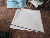
I am impressed how much information I am getting from taking a few drawings and sending them to a CNC router and cut many parts out of a 4X8 sheet of Masonite.
This first batch was done in two steps, the first intention was to make a template of the wing that would slide onto the wing mount tabs of the fuselage. I am impressed how much there was to learn with this first step. without even edge finishing the cut part it fits over the weldment pretty damn close. The rear spar tabs are .013 out on one side and .011 out on the other from the template. Probably much of that was either when the weld jig was made or when I drew this template at a later date.
I think of how many times I have read recently of people discovering their mount tabs are an eighth or a ¼ out of spec after welding. Gad I have no clue how someone can distort something that much and later actually fly the thing. Not me mate.

One of the needs for this template is to weld in the ¾" Sq tube that extends aft of the rear spar. This tube is formed with a gentile contour to conform with the top surface of the wing, but needs to sit down 0.150 so it is under the polycarbonate top of the cabin, should I decide to have the aft section clear.
With this template in place I was quick to realize the two changes in airfoil will need a change to the aft curvature since I have both moved the C/P back and changed to a non cusped airfoil. So it will be back to the press to reform these tubes.
The small hole in the template aft of the rear spar is where the flap torque arm pivot is to be. The hard point of which is a threaded bung in these tube I need to fit precisely. With this tooling, should the parts not line up perfectly it will be easier to change the drawing to conform with the welded assembly.
I chose to draw up for another cut for a template that will slide fully up to the top structure with the top curve lowered the 0.150 to what I actually need to build too, the inside structure and not the outer skin of the wing.


This will allow me to more accurately build out the upper structure of the cabin area.
Other parts I cut out were full size patterns of the wing and flap system, these will allow full actuation of the flaps from the handle through the full 80° range of travel as well as spare parts to allow for changes of pivot location such that the fore flap needs a different travel ratio or pivot location once determined by airflow analysis when done later this year.

The other small bits above are bellcranks for both the rudder pedals and the aft end of the pushrod bellcrank for the elevator.
The next batch are templates for the ribs for the vertical fin and the inner and outer of the horizontal.

As well as a box full of other tools and templates,

I am thinking since I am on a roll with this Gerber router I will move right into cutting templates for the elevator and rudder build in Masonite as well as making wing rib tooling in some 1" MDF and the tail ribs in ¾" material. The rudder and elevator ribs will be welded up in C channel.
No tooling at this time for ailerons and flaps since they will more than likely be composite structures.


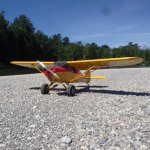
 Most all the work on my Quickie was done in '84-86. Mine has a Rotax 447on the nose and is the first customer plane built with the Carbon spar and new airfoil. It also has drooping & reflexing ailerons.