• If You Are Having Trouble Logging In with Your Old Username and Password, Please use this Forgot Your Password link to get re-established.
  • Hey! Be sure to login or register!

Lowrider LSA

That amount of differential is good for counteracting the adverse yaw. The secondary stops are at the control stick. My Cub doesn't have any at the surfaces. Don't worry about having too much as that will be controlled by pilot input. It is too little travel which would concern me. When rigging controls with stops at both ends of the system the surface stops are limiting with a small gap at the stick stops to ensure that the surface will move to it's limits.

I used a film camera for my pictures. Remember those? And pages of lined paper with a date, brief description of task and time spent. Put it all together in a loose leaf binder along with any sketches. DAR said that I didn't need all of that. Your DAR may have a different point of view, ask him.
 
Last edited:
Don't worry about having too much as that will be controlled by pilot input. It is too little travel which would concern me.

x2

Gearing ratio is key to a twitchy feeling airplane. If you're nervous about that I wonder if you could put a few extra holes in the bellcranks to allow you to adjust the gearing ratio after test flight.

Experienced builders, has this sort of thing been done before on this type of build?
 
Hi Sky!

I don't have stops at the stick per se. Since I'm using push/pull rods and not cables and pulleys the limit is pretty well set by how far the rod can move at the stick end. My thoughts were that I can put in stop bolts at the bell crank in each wing and be able to access them thru the inspection panel in the bottom of the wing and I would really only need to use them if the deflection of the aileron is excessive.

I left my stick extra long (as most men would desire) so it is limited in side to side motion by the sides of the fuselage and door on the right side and the amount of throw in the rod is set by where it is attached to the stick. When I designed the stick I made it so it achieves max movement just short of hitting the fuselage allowing about 4" on each side for hand clearance. The extra length also adds leverage which shouldn't be needed. I will cut the stick if it is too long but I usually fly with my hand lower on the stick so it probably won't be an issue and my push to talk will be on the throttle and not the top or front of the stick.
 
Cam,

I'd need to look at the drawings but I don't think there is an adjustment involved for the ailerons. My concern is the extra large size of the aileron and it's affect on roll. Your idea of having extra holes in the bell crank is a good alternative to a stop bolt. I'm building all the parts so I can include that option when I make them...thanks for the thought!!
 
On second thought I have it backwards. The primary stops will be at the surfaces. In reality for your purposes you only need them to prevent you from over controlling thus doing some damage. I set mine for as much travel as I could get.
 
Film camera eh! I still have mine and one of them instant things that used to be high tech by giving you a picture in 60 seconds. Guess I'll put them in my will to go to a museum when I check out.

Sounds like if I don't exceed the limits set on the drawing it won't cause any real issues even though they do have more surface area.

Thanks and off to the shop to scratch my head some more...building airplanes is a lot of fun and a learning experience!!
 
...... Since I'm using push/pull rods and not cables and pulleys ......

Been following your build but evidently not close enough. Did you already talk about you aileron system and I missed it. Are your push/pull rods from the aileron to the bell crank, or all the way done the wing?

Doug
 
I haven't discussed them in any great detail Doug. These are flexible stainless control rods that run from the bell crank to the control stick on both wings. I'm using them to do away with the cable and pulley system which I believe is more complicated than it needs to be. Rudder and elevator are also run by these rods and it makes a nice simple installation and I believe less prone to "control slop" and maint. issues. I do use a CM tube from the bell crank on the elevator horn to simplify that operation. Each of the rudder pedal pulls the rudder horn and the aileron rods will pull the bell crank which will operate the aileron in one direction and push the other aileron in the opposite direction.

I started on my wings and got tired of riveting and started welding tube on the fuselage. Now, I'm back on the wings which are a pain to do by myself and #2 son moved to his own place so I don't have ready supply of semi-skilled assistance. My wife helped me skin the wings on the RV-4 I built but she will have nothing to do with these wings...she says her ears are still ringing from the last time she help rivet. I thought everyone's ear were suppose to ring all the time. She says I should have bought a Zenith 750 kit and I could use all pulled rivets...a little late for that option now.
 
Cool, I will be interested to know how that works out. I always liked the feel of push/pull tubes like in a RV but could not come up with a simple monkey motion to use them in a high wing.

Doug
 
Lowrider: This will add to the mix and give you something to think about! BackCountryCubs prototype LSA uses carbon control surfaces and carbon ribs on an aluminum spar. LE slats, also carbon, are manually controlled via a torque tube, and retract perfectly flush in cruise. Double slotted fowler flaps, with drooping ailerons, 60 degrees. Carbon sheeted wing surfaces, the fuselage more or less conventional. 780 lb projected empty weight, using a 145 horse turboed Rotax. 12 mph stall and 145 cruise. I was at the factory this weekend, and no it has not flown yet, but soon, very soon. That's a 145 horse slat equipped Rans S-7 in the background, it's the preferred mount for coyote getting I'm told, it had a shotgun inside anyway.

Any more info on these flaps?
 
I had (as in past tense) real thoughts about adding Zenith 750 slats at one point...resized to fit my wing. That thought lingered for maybe 6 months but I have since been able to forever (?) remove it from my mind. DON'T bring it up again please...I can't handle it!

My flaps are designed but not skinned and the hinges and control rods are working just fine. I will need to build the connection between the flaps once the wings are on the fuselage and the 4 position handle to operate them. They are conventional flaps...maybe Fowlers on the next build...but that may be a single seat like an RV 3 or something. I made my door big enough to shoot out of but it needs a barrel stop to prevent tire and strut mishaps.

Back to ailerons...this probably doesn't make any sense, but does anyone use a light spring on the ailerons to keep them in neutral position? The control stick will have the "V" stick lock when on the ground. Any thoughts?
 
This has been a frustrating but ultimately productive 2 weeks. Building and fitting the aileron has been a challenge and time consuming to say the least but I'm at a point where I'm declaring victory anyway. The aileron stops are not in but the durn thing functions as it should and surprisingly very easily with the push/pull rod which makes me thing the stick will be very sensitive when it's all installed. Total movement at the top of the stick is right about 13" which seems about right and does so with very little pressure. The air resistance will of course change the feel at the stick and I won't really know how much until it's in the air...so...I'll do fine tuning at that point.

These pictures are not exactly representative but gives an idea. Deflections are not set and there is no one to hold the rod in the proper location to show the way the ailerons will look with the stops in place. I can easily exceed the plans but I'll use those figures until they are proven wrong for my layout.

aileron 008.jpgaileron 010.jpg
 

Attachments

  • aileron 008.jpg
    aileron 008.jpg
    83.6 KB · Views: 126
  • aileron 010.jpg
    aileron 010.jpg
    48 KB · Views: 153
Variable Drooping ailerons would be fairly simple to rig when using push pull cable. Hope you are not wild about your bellcrank.
 
Thanks for being observant gents!

The bell crank is actually a proto-type to get the angles and spacing right. It's my third iteration so using flat iron was easiest to make one from. The real one will be 3/8x0.035 CM with a real bearing on a 3/8" AN bolt maybe supported top and bottom. I figured I'd get caught using a grade 2 bolt for a pivot pin. I had a pretty hard time getting this contraption to work out but I think I have the distances and the 90 degree will work on the 3rd attempt.

Other than than Mrs. Lincoln how was the play?
 
Sky/Don,

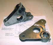
I went to the shop early this morning and started putting together what had planned to use for the "real" bell crank and I quickly decided it was going to be pretty heavy the way I envisioned it. The plans show 1/2x035 CM with flat material welded on the ends to accept the rod ends. That would certainly work but transitioning from the tube that will hold the bearings to flat is almost a straight taper to allow room for the rod end to be attached and plenty of clearance. I was thinking way heavy construction above and beyond what is appropiate.

I thought someone must have designed another way to build a simple bell crank so I pulled up my Northland Super Cub drawings and found that dwg 40092 shows a cast alum bell crank that was used in the SC. I looked at some supporting things like pulley brackets and the like and found they were all made from 0.032 or 0.045 sheet in 1025 steel. They had bends in them which would stiffen them some but they look pretty like pretty light construction for the most part.

That said, I have some 1/2" x0.125CM and a sheet of 0.100 CM that I could make a bell crank from and put in diagonal bracing and 90 degree brace that would run from the tube containing the bearings to the end where the rod bearings would attach...all welded together it would be very rigid and prevent any chance of twisting. So how does that sound?

I though I had 3/8" ID bearings but they turned out to be 1/2" so I need to order smaller ones anyway so no hurry.
 
This is an overbuilt version of what I had in mind. The attach points are 90* apart. You could use a single layer of relatively thin material. IF you bend the three edges up or down 90* each leg will be considerably stiffened. The hole in the middle only serves to reduce weight. IF you use thin material you could stiffen the edge of the hole by flanging the edge. If you make a two piece such as this, you could get away with quite thin material bent along the edges for stiffness.

137_Welded_Bell_Cranks.JPG

Your original "L" shaped one needs to be changed to a triangle with stiffening flanges along the outside edge. Your pivot bushing is satisfactory though it ought to have a means of lubrication since it is very long and difficult to lubricate the entire length. As you have shown it, each narrow leg could twist and then bend under load.

This is only one idea. There are many possibilities.
 

Attachments

  • 137_Welded_Bell_Cranks.JPG
    137_Welded_Bell_Cranks.JPG
    227.9 KB · Views: 111
If you can get the bell crank mount or the mount where the push-pull tubes are secured to move along with the flaps then you can get drooping ailerons. A lot tougher to do with cable type controls than with push pull rods. if there is a Murphy rebel around take a look at the way they did their flap an aileron drive.
 
Sky,

I can easily bend the edges of 0.050 CM is that adequate or do I need to weld a 90 degree flange on the edge to provide some serious stiffening? I can do zerks to do a better job of lubing. I also thought about a 0.015 teflon liner between the tube and bolt. I think I have some somewhere left over from a boat repair issue awhile back...it's slick as greased owl snot.

Don,

I understand the concept but I need to think about this some. I have an overbuilt wing for the LSA weight limit so I'm reluctant to add more complexity and weight to the plane. How much lift vs drag gain is there with the droops? It would seem my 8' flaps should provide all that's needed even if I go to floats...but then who knows until you try it. My '48 170 has the little mini flaps and they do very little on that wing. Using the Riblett wing and flaps I think there is a balance there between cruise and slow flight...we'll see when I get it done. Gotta do some research on droops...what's the real gain????
 
If you can get the bell crank mount or the mount where the push-pull tubes are secured to move along with the flaps then you can get drooping ailerons. A lot tougher to do with cable type controls than with push pull rods. if there is a Murphy rebel around take a look at the way they did their flap an aileron drive.
I like this idea.
 
Low,

Do a Google search on drooping ailerons and you will find all sorts of stuff from this site. My experience is with Cessna Rstol and yes it reduces stall speed/landing speed.

Build aileron control attachment so you can easel change from 0 droop to 10/15 on the ground. Then have flap setting the same. Just a thought.
 
Lowrider,

I'm mimicking the original Piper flap bell crank with .100 4130. It will have a flange welded around the perimeter, and a stiffener running from the pivot to the inside of the dog leg. I plan to drill some holes similar to the aileron horn to waste some time lightening it. It should be comparable in weight to the original. If I get it hacked together this week, I'll put it up. Seems like Javron makes a pretty simple one out of steel, maybe Bill Rusk has a picture of his.

Thanks,

Jim
 
Thanks Jim! I cobbled up a triangle shape with flanges bent all around. I primed it and I'll get a picture in the morning after bacon and pancakes.

Sky/Don,

OK, I'm still thinking but have come up with an idea. How about the bell crank mounted just as it is with a sliding tube that the brace can move thru to adjust the angle of the droop? Along with that what if I put a jack screw on top operated by an electric motor with limit switch at the two ends of travel. It could be controlled with a two way switch on the stick or throttle. That way it could be run from zero to say 30 degrees droop depending upon conditions and desire. I guess a "flap position indicator" could be used to keep track of the droop.

Still thinking....
 
Sky,

I can easily bend the edges of 0.050 CM is that adequate or do I need to weld a 90 degree flange on the edge to provide some serious stiffening? I can do zerks to do a better job of lubing. I also thought about a 0.015 teflon liner between the tube and bolt. I think I have some somewhere left over from a boat repair issue awhile back...it's slick as greased owl snot.
Heat the edges and bend a radius. A 1/8"-3/16" flange should be sufficient. The teflon should work providing you do get a good fit without slop. I would hate for that bolt to get a little rust on it getting stuck in the pivot tube. That would cause you more grief.
Low,
Build aileron control attachment so you can easel change from 0 droop to 10/15 on the ground. Then have flap setting the same. Just a thought.
Make the drooping function so that it can be operated independently of the flaps. If the ailerons are drooped in a strong crosswind your control will be compromised. Also if the ailerons are drooped during landing you will require more up elevator to hold the tail down since the aileron droop moves the center of lift on the wing aft.

ps, I'm a big fan of drooping ailerons with the wind on the nose. They do make a considerable reduction in % of stall speeds and angle of climb improvement.

pps, The aileron droop on my 185 is placarded to use for take off only.
 
Last edited:
I'm on the ragged edge of being convinced that drooping is worthwhile.

Dave Calkins talked me into the full length ailerons and he is a big supporter of drooping 10 or more years back. He seems to have left the site since I haven't seen much of him lately.

Having many others use and love the droop and since I'm at a point in construction where it would be fairly easy to incorporate it into my ailerons I guess I should proceed. 2 or more questions persist:

1. It seems that the ailerons MUST act together being deployed or retracted to avoid an imbalance in lift/control. How to do that? My answer would be an electric motor driving a screw on the bell crank support to move the ailerons up or down. One switch to control motors in each wing in unison.

2. What is the control loss with the ailerons in the down position...say 30 degrees? Normal down deflection is 18 degrees and up is 23* so we get 48* on the down alileron and I guess effectivly only 7* up. Or am I missing something here? I guess the down aileron side will lift the wing anyway but it seems the control is not the same as ailerons that are in the up position. If you have a gust against the down aileron do we end up with an over control situation and roll the plane more than intended?

More questions to come I'm sure.
 
1. If they do not act together, they are just ailerons.

2. Total droop wants to be in the 12-15 degree range. That will give you 30-33* max down with full aileron throw and 8-11* up when drooped. 8-11 up is not much at low speeds particularly when the boundary layer starts to separate moving the air away from the aileron.

Remember that it is the up aileron which does the most work when rolling the airplane by dumping lift on that wing. The down aileron provides some lift while increasing the angle of attack and drag of the outboard portion of that wing, thus increasing stall speed of that section of wing. A down force counteracting the minimal opposing force of the opposite aileron.
 
Back
Top