• If You Are Having Trouble Logging In with Your Old Username and Password, Please use this Forgot Your Password link to get re-established.
  • Hey! Be sure to login or register!

Olibuilt 's New Cub project

Thanks to Dan Gervae idea, I've searched and found this from CubCrafters 180hp Top Cub on Wipaire 2100 Amphibian floats:

Capture d’écran 2022-03-25 à 6.28.12 p.m..png

Capture d’écran 2022-03-25 à 6.27.58 p.m..png

Capture d’écran 2022-03-25 à 6.27.38 p.m..png
 

Attachments

  • Capture d’écran 2022-03-25 à 6.28.12 p.m..png
    Capture d’écran 2022-03-25 à 6.28.12 p.m..png
    124.4 KB · Views: 964
  • Capture d’écran 2022-03-25 à 6.28.12 p.m..png
    Capture d’écran 2022-03-25 à 6.28.12 p.m..png
    124.4 KB · Views: 70
  • Capture d’écran 2022-03-25 à 6.27.58 p.m..png
    Capture d’écran 2022-03-25 à 6.27.58 p.m..png
    65.8 KB · Views: 964
  • Capture d’écran 2022-03-25 à 6.27.38 p.m..png
    Capture d’écran 2022-03-25 à 6.27.38 p.m..png
    115.3 KB · Views: 956
That is some knowledge and experience, thanks for sharing with us. Your advices are always very helpful for me and others.

Now, for a regular average 150-180hp Super Cub on Wipline 2100 amphibious floats:

1: Where would you put the step in relation to the 63" wing chord, float top level?
2: How many degrees from the float top to the bottom of wing ?
3: Rudder height from ground, float top level?

So far, what I've found:

1: step @ 38.5% to 50% of wing chord
2: 3.5* to 5.9* float top to the bottom of wing
3: 10'4" to 10'6.5" (easy part hahahah)

On wheels:
View attachment 60659


On Wip's 2100A:


View attachment 60656

View attachment 60657


My drawing looking for answer:
View attachment 60658
Too much information.
 
Throwing a percentage of chord as a solution of step location is only throwing darts at a dart board unless it can be backed up with good documentation. So far I've seen none.

Step location and water handling characteristics are based upon the flying weight and center of gravity of that particular combination.

The fish mouth angle is largely based upon your desire for short take off, good cruise speeds, or a compromise between the two. Only you can answer that question. My 180 hp Cub has 3.5 degrees between the float deck and the bottom of the wing. You with the slats and perhaps a desire to get out of the water sooner may want more. I am happy using half of a 900 foot long pond with my setup. Generally with most floats, the float deck is parallel to the keel. This is why we are measuring the float deck. It is really the keel which we are concerned with. Remember when all is done, add 8 degrees to the chord line angle. This is the angle the wing will be at while you are accelerating on the "sweet" spot on the step. This will be the angle with which to determine your wing's performance. Using flaps, increases this angle. The slats won't help until after you are in the air with the nose further up. Getting the nose high enough while on the water for the slats to help will require dragging the tails of the floats in the water. Not a good idea.

The height of the plane above the floats is dictated by the diameter of the propeller when the plane is at rest in the water. 15" tip to water minimum.

To date the only documented method of locating the step I've seen is that from Dave Thurston's book. Post #626

Use your weight and balance, not that from someone else's airplane. That is in post #627 from the numbers you gave me. Based upon the weight I used for pilot and passenger your CG for the calculation of the 10 degree arc is 17". From the pictures I've seen of you and your lady, the 150 pounds may be high. Place that 17" from the wing leading edge on the window sill for the vertical location. Draw your 10 degree line from that point. That is a safe starting location for the step. The step being further aft helps in getting on the step with a low horsepower engine. Too far aft and you could have porpoising issues. Too far forward increases the time to get on the step. The length of time to get on the step is a prime contributor to the length of the take off run. You have to move against a lot of water getting up on the step before the drag is reduced enough to accelerate to flying speed.
 
I've went to measure a set of Wipline 2100a rigged for a PA18-180hp.

Float CG was at about 18.5" front of the step for Wipline, and suppose to be between 17" and 19" for Clamar.

Step was at 24.5" of wing leading edge, straight down, float top level.


My plane is a slow plane, with slats.

This is what I came up for rigging plan, I've sent to Clamar.

At 6 degrees, my sketch raises the front of the plane and lower rear.
That should give me about 73" under front wing spar to float top.
120" rudder top to ground.


Paintbrush drawing that I did my best to try to keep to scale.

You can see Clamar suggested rigging and my suggested rigging


6.0* final.jpg

rear strut final.jpg
 

Attachments

  • 6.0* final.jpg
    6.0* final.jpg
    167.4 KB · Views: 782
  • rear strut final.jpg
    rear strut final.jpg
    42.8 KB · Views: 783
6 degrees to the bottom of the wing will give you 7.77 degrees to the chord line. This is a lot. That will give you an angle of attack while you are on the step of 15.77 degrees. That means you will have to land each time with the nose at least that high. If not you risk digging in the bows. If that is what you want, make sure that you can stretch your rear strut as much as 2". In the end, I think you will be happier with about 1-1/2 degrees less.
 
6 degrees to the bottom of the wing will give you 7.77 degrees to the chord line. This is a lot. That will give you an angle of attack while you are on the step of 15.77 degrees. That means you will have to land each time with the nose at least that high. If not you risk digging in the bows. If that is what you want, make sure that you can stretch your rear strut as much as 2". In the end, I think you will be happier with about 1-1/2 degrees less.

Bill Rusk is at 5.9. So my 6 degrees is not that much ??

Rear adjusting holes at .5" apart. So from 4.5 to 6.5 degrees.


Where is Amy Gesch ???
 
Build a set of temporary adjustable rear struts out of square steel tubing with turnbuckle style ends then find the length that works best for your setup, then cut your final struts.
 
I was away from home all summer. I'm now back and installing Clamar 2180 amphibs under that red plane.


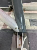
Do you guys think it is an acceptable method to attach the 5/16 fly wire clevis to a 5/16 eye bolt, like shown in the picture bellow?

IMG_8663.jpg
 

Attachments

  • IMG_8663.jpg
    IMG_8663.jpg
    55.6 KB · Views: 1,350
Last edited:
Oli,
You have placed a bending load on the eye bolt. This is an engineering no no. The load path should be in a straight line from your cross wire to the float deck fitting. The picture doesn't show the aft side of your strut to float fitting. You would have a better load path if you had a wire pull strap under the nut on the horizontal bolt through the deck fitting. Attach the cross wire to the wire pull strap. This will give you a straight pull.

Will the way you have it fail? I can't answer that question other than to say that is not the way it should be done.
 
I agree, this is why I ask.


Look at a few others. Do you think it is stronger with a 3/16 bent stainless steel pull strap closer to the bolt? I do.


Clamar 2180a to strut
IMG_6438.jpg


Wipline 2100a to spreader bar
wipline lower flywire.jpg


Clamar 2180a to strut
float-rigging-2-pickup.jpg


Clamar 2180a to spreader bar
IMG_7663.jpg
 

Attachments

  • IMG_6438.jpg
    IMG_6438.jpg
    66.4 KB · Views: 60
  • wipline lower flywire.jpg
    wipline lower flywire.jpg
    60.3 KB · Views: 63
  • float-rigging-2-pickup.jpg
    float-rigging-2-pickup.jpg
    118.5 KB · Views: 47
  • IMG_7663.jpg
    IMG_7663.jpg
    322.5 KB · Views: 54
Last edited:
This is a cross wire attachment on an EDO 2000. The flat strap between the wire and the spreader attachment bolt is called a wire pull. Notice the thick piece under the head of the bolt with the curved section against the wire pull. This is to prevent the bending of the bolt while pulling at an angle.

20221207_172537.jpg This is another example of attaching a cross wire. 20221207_172816.jpg
 

Attachments

  • 20221207_172537.jpg
    20221207_172537.jpg
    43.2 KB · Views: 55
  • 20221207_172714.jpg
    20221207_172714.jpg
    37 KB · Views: 45
  • 20221207_172816.jpg
    20221207_172816.jpg
    46.1 KB · Views: 53
Your trying to lock the floats into a rigged position, why run the wire to an aluminum strut when it would be easy to run it to the float anchored to the float attach bracket?

Glenn
 
Think shake during takeoff or landing when attaching tie wires. One float gets hit then the other by any waves, gets worse with a heavy plane and large waves. The whole plane can rock from one float to the other and the wires have to alternately absorb and transfer that momentum to something capable of handling it over time. I'd want long term tough mounts.

Gary
 
Your trying to lock the floats into a rigged position, why run the wire to an aluminum strut when it would be easy to run it to the float anchored to the float attach bracket?

Glenn
Glenn,
That eye bolt is going through the strut and the fitting which then attaches to the deck fitting. Pretty solid.
That eye bolt would be suitable to attach the crosswire to the upper fitting since the cross wire pull would be a in a straight pull not a bending load at the upper location.
 
Wire pulls are the method I used…very solid install.
0FB0E377-3FC2-4B3D-AB18-CEAA5EF43C67.jpg
I agree with Pete about the eye bolt…not the best application maybe. I guess any of the options you illustrated as far as the location to attach the fly wires are ok…it’s a personal preference. My Baumanns are attached to the deck fitting and that works fine too. Aerocet does the deck fitting on the 1500 install.
F8A01925-3E08-419F-AD04-98F4419AED2E.jpg
my Mead deck fittings were a 4 bolt design so I used the bottom strut bolt to keep the pull aligned with the strut.
 

Attachments

  • 0FB0E377-3FC2-4B3D-AB18-CEAA5EF43C67.jpg
    0FB0E377-3FC2-4B3D-AB18-CEAA5EF43C67.jpg
    101.4 KB · Views: 77
  • F8A01925-3E08-419F-AD04-98F4419AED2E.jpg
    F8A01925-3E08-419F-AD04-98F4419AED2E.jpg
    42.7 KB · Views: 62
I plan to use those stainless steel hardware for my 3/32 float rudder cables.


How can I crimp this little ball shank??

317952789_474551568094006_7156219968451290492_n.jpg
 

Attachments

  • 317952789_474551568094006_7156219968451290492_n.jpg
    317952789_474551568094006_7156219968451290492_n.jpg
    103 KB · Views: 1,846
I drilled the holes in the rigging struts today.


Airplane is hung up as per previous plan.

IMG_8683.jpg


Formed poster board paper to make adjustable strut template.

IMG_8679.jpg

IMG_8680.jpg


A simple wood jig was made to have all the holes straight.

IMG_8678.jpg
 

Attachments

  • IMG_8678.jpg
    IMG_8678.jpg
    116.9 KB · Views: 55
  • IMG_8683.jpg
    IMG_8683.jpg
    71.4 KB · Views: 1,714
  • IMG_8679.jpg
    IMG_8679.jpg
    113.8 KB · Views: 68
  • IMG_8680.jpg
    IMG_8680.jpg
    65.4 KB · Views: 62
Transition from cardboard to aluminum went good. I'm going to open the struts gaps to about 1/8".

IMG_8686.jpg

IMG_8687.jpg
 

Attachments

  • IMG_8686.jpg
    IMG_8686.jpg
    73.3 KB · Views: 52
  • IMG_8687.jpg
    IMG_8687.jpg
    58.6 KB · Views: 58
Looking good! I have to say, I really had fun rigging my floats. I learned so much from all of you here on this site. Oli, do leading edge slats change your AOA significantly on landing? I’m interested to see how it performs….it really looks nice on those floats. Great job
 
Oli, do leading edge slats change your AOA significantly on landing? I’m interested to see how it performs….it really looks nice on those floats. Great job

I can land with a very high nose up attitude. Won't be possible without hitting float heels..

That is why I've went with 6 degrees. Hope it performs good on water and on land, will see next spring..
 
That is why I've went with 6 degrees. Hope it performs good on water and on land, will see next spring..
6 degrees will produce high drag with increased nose down pitching moment for cruise and climb. In addition to the high drag for cruise you will need a lot of nose up trim which is more drag.
 
If 5.5 degrees works for Bill Rusk, it should work for me, and Clamars have smaller flat tops.

I really hope the plane will takeoff and land short, even with the added weight...


I have no experience at all with amphibs, but this is my kind of landing (without the bouncing nose wheels..)


See at 0:40
 
Back
Top