
You are using an out of date browser. It may not display this or other websites correctly.
You should upgrade or use an alternative browser.
You should upgrade or use an alternative browser.
Building a Javron Cub
- Thread starter Bill Rusk
- Start date
pittsdriver
MEMBER


mike mcs repair
Registered User
chugiak AK
Jay cut the panel for the Aussie Cub. Sent it to Javalina in Texas and they laser etched all the stenciling. Don View attachment 8979
beautiful !!
Roger Peterson
Registered User
Sweeny, Texas
Looking good Bill. Gives me some incentive to keep going. Keep taking picts and posting.
MainlandCub
Registered User
New Zealand
Jay cut the panel for the Aussie Cub. Sent it to Javalina in Texas and they laser etched all the stenciling. Don View attachment 8979
Nice. Where did you get that turn and slip and what make are the engine dials?
Thanks,
Andrew.
Olibuilt
MEMBER
Montreal, Canada


Bill Rusk
BENEFACTOR
Sandpoint, Idaho
That is where the aft spar was trying to twist, on the Load test that Jay ran, and as soon as it gets out of vertical alignment it will fail.
Often the only difference between an aerobatic wing and a standard wing is the number of ribs. The actual spar may be the exact same size. Well, you might ask, ribs don't add any strength so why add ribs? Would it not be better to make the spars bigger to handle the increased G loads? The extra ribs keep the spars in alignment, preventing them from twisting or bowing out of alignment, and thus setting up a failure. It is all about keeping that spar straight and vertical.
Hope this helps
Bill
pittsdriver
MEMBER
Nice. Where did you get that turn and slip and what make are the engine dials?
Thanks,
Andrew.
Got the Turn and Slip from a guy in Australia. It also has a starter pushbutton from a Spitfire. Gauges are UMA but I would not use UMA again. All of the guages were sent to an instrument shop and refaced so all the colors and fonts are the same. For kicks they also have a logo we made up "Chapton Hill Co
Limited Sydney." Also the vertical card compass has a Cub silkscreened on the glass as a pointer instead of the usual swept wing jet. All just fun stuff.
Bill, I really like that wing. Can't wait to see the empty weight. Don
Bill Rusk
BENEFACTOR
Sandpoint, Idaho
Hi guys, I'm back
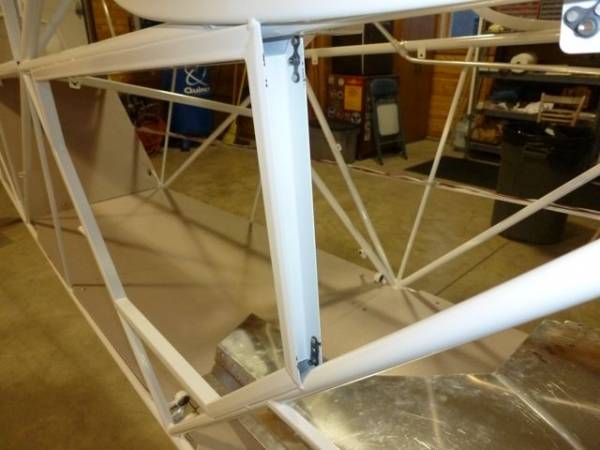
Lets talk a little about fuel lines and routing. All fuel lines must be secured and well protected from chafing. You can't just let them rub against things.
When you can use adel clamps like this it works well. This is the right rear pick up line going aft around the baggage area. I ran this line outside as I will be using a fabric headliner and this routing will give the least profile. It will just follow the bottom of the wing to fuselage junction. It will only be noticeable to someone who really knows cubs and is very observant, like Jason Gerard or Steve Pierce.

Another photo of the same line.

Now here is a mistake. I had a helper and I did not give enough direction. The line needs to be as low as you can get it to the structure to ensure that it is even with, or below, the outflow from the tank. The picture below shows it about an inch above the structure. Not good......

This is where it should be ...... note it is sitting on the structure.....

All of your fuel lines should be as low as you can get them at the pick up points and they should all go in a continuous line downhill to the low point, drain, fuel valve etc. You do not want a place for water to gather except at the sump. There are places where the adel clamps just don't work out, so here is another idea. Wrap the fuel line with cloth tape, or I like to use plastic tubing like Nylaflow, then wrap it to the structure with flat rib stitching cord. Smear a little epoxy over it all when done and it will hold quite well and have a minimum bulge under fabric. Tie wraps are not such a good idea unless you protect the fuel line quite well as they will chafe right through aluminum lines (steel too).


Here is a place where I used cloth tape and smeared a little epoxy on there as well.

This is the right rear line again. It will transition inside to prevent showing through the fabric on the outside. This will have a different routing if you are going to use a metal headliner. I will have a bulge for a few inches inside the headliner until it goes behind the side panels, but again I don't think it will be all that noticeable. Note that this is the only junction, or joint in my fuel lines. Each junction is an opportunity for a leak and also quite possibly a reduction in flow. Even if you have to scrap a little fuel line and re-bend em a few times, try to get the lines in without a bunch of joinings.

Another rib stich cord attachment.

Not the best picture but the left rear line runs down in the gap between the window channel and the structural tube. This is an easy one and when its all covered and painted no one will know its there.

More to follow
Bill
Lets talk a little about fuel lines and routing. All fuel lines must be secured and well protected from chafing. You can't just let them rub against things.
When you can use adel clamps like this it works well. This is the right rear pick up line going aft around the baggage area. I ran this line outside as I will be using a fabric headliner and this routing will give the least profile. It will just follow the bottom of the wing to fuselage junction. It will only be noticeable to someone who really knows cubs and is very observant, like Jason Gerard or Steve Pierce.
Another photo of the same line.
Now here is a mistake. I had a helper and I did not give enough direction. The line needs to be as low as you can get it to the structure to ensure that it is even with, or below, the outflow from the tank. The picture below shows it about an inch above the structure. Not good......
This is where it should be ...... note it is sitting on the structure.....
All of your fuel lines should be as low as you can get them at the pick up points and they should all go in a continuous line downhill to the low point, drain, fuel valve etc. You do not want a place for water to gather except at the sump. There are places where the adel clamps just don't work out, so here is another idea. Wrap the fuel line with cloth tape, or I like to use plastic tubing like Nylaflow, then wrap it to the structure with flat rib stitching cord. Smear a little epoxy over it all when done and it will hold quite well and have a minimum bulge under fabric. Tie wraps are not such a good idea unless you protect the fuel line quite well as they will chafe right through aluminum lines (steel too).
Here is a place where I used cloth tape and smeared a little epoxy on there as well.
This is the right rear line again. It will transition inside to prevent showing through the fabric on the outside. This will have a different routing if you are going to use a metal headliner. I will have a bulge for a few inches inside the headliner until it goes behind the side panels, but again I don't think it will be all that noticeable. Note that this is the only junction, or joint in my fuel lines. Each junction is an opportunity for a leak and also quite possibly a reduction in flow. Even if you have to scrap a little fuel line and re-bend em a few times, try to get the lines in without a bunch of joinings.
Another rib stich cord attachment.
Not the best picture but the left rear line runs down in the gap between the window channel and the structural tube. This is an easy one and when its all covered and painted no one will know its there.
More to follow
Bill
Bill Rusk
BENEFACTOR
Sandpoint, Idaho
Here are some photos of my interior panels. My floor sits on the lower longerons so I have to box the cables. This is really a pain and I'm not sure it is worth the time and effort on this one to save a couple of pounds. Most extended baggages have a shelf built in above the lower longerons so the cables run under the floor. It would be a lot easier to do it that way. But I'm pretty nutty about weight so.........
This panel was cut in error so I had to rivet on a box. This will be covered with fabric so it will not show the seam or rivets when complete.

End view of the boxed cable.......

Outside view of boxed area......

Photo showing nutplate location ideas......


This is the left rear panel (not complete) but it shows the shape. Note on this one I was a little more careful and cut it so I could do all the bends for the box and I did not have to rivet on a separate piece. I still need to box the rear flap pulley. Again, this area, and forward, the interior panels are .016 aluminum and they will have a tweed type fabric glued on which will give a more refined finished look to the interior. It will add a little weight but I just like it better that way. My opinion only.

Forward panel. I put a little bend in the middle so it fits close to the diagonal tube.

Hope this helps
Bill
This panel was cut in error so I had to rivet on a box. This will be covered with fabric so it will not show the seam or rivets when complete.
End view of the boxed cable.......
Outside view of boxed area......
Photo showing nutplate location ideas......
This is the left rear panel (not complete) but it shows the shape. Note on this one I was a little more careful and cut it so I could do all the bends for the box and I did not have to rivet on a separate piece. I still need to box the rear flap pulley. Again, this area, and forward, the interior panels are .016 aluminum and they will have a tweed type fabric glued on which will give a more refined finished look to the interior. It will add a little weight but I just like it better that way. My opinion only.
Forward panel. I put a little bend in the middle so it fits close to the diagonal tube.
Hope this helps
Bill
Greg Campbell
MEMBER
Oklahoma
Bill, Your project is looking really great. I just finished running
Fuel line. I haven't insulated it yet. Where do you buy your Nylaflow?
Fuel line. I haven't insulated it yet. Where do you buy your Nylaflow?
Bill Rusk
BENEFACTOR
Sandpoint, Idaho
Greg
I got it at Spruce. Just be sure to get the ID of the nylaflow to match the OD of the fuel line. Split it open with a single edge razor and be careful or have Kimmie standing by with bandaids.
Doc - man,... I just could not bring myself to throw away that big chunk of aluminum. That stuff is really getting expensive. I think CC is using an all nylon poly flow type tubing now. Might be lighter........oh boy.... here we go......
Bill
cubdriver2
FRIEND
upstate NY
Bill I wonder if heat shrink tubing over your nylaflow would capture it to the fuel line before tying it off? Looks great, thanks for sharing.
Glenn
Glenn
Steve Pierce
BENEFACTOR
Graham, TX
Bill, How will you attach the wing root fairing to the fuselage with the fuel line on the outside of the 3/8" channel?
docstory
Registered User
Anchorage, AK
Just bustin' yer chops, man.Doc - man,... I just could not bring myself to throw away that big chunk of aluminum. That stuff is really getting expensive. I think CC is using an all nylon poly flow type tubing now. Might be lighter........oh boy.... here we go......
Bill
You mention the weight factor a lot. Every little bit helps.
Gordon Misch
MEMBER
Toledo, Wa (KTDO)
Tied my liines off with koroseal with a cross-wrap for stand-off, so no need to sleeve. I like koroseal because it's somewhat elastic so stays tight - no chafe. But it's bulky compared to the rib lacing cord - -
aktango58
FRIEND
18AA
Bill, How will you attach the wing root fairing to the fuselage with the fuel line on the outside of the 3/8" channel?
I was thinking that the fuel line needed to turn in by the square upright...
MainlandCub
Registered User
New Zealand
Heat Shrink.
Yes I agree. I use some sort of plastic tubing where you want a lot of protection held in place with heat shrink. There are two types of heat shrink I can get here, one has glue on the inside that activates with heat and is heavier wall than standard heat shrink. This holds in place really well and is good enough protection on its own in many instances. And if you want extra protection, put on two layers. I would probably want heat shrink under the P-clips too, but then that is just me...... You need to plan ahead a bit with the heat shrink and slide it on before doing the flares or beads.
Great pictures, again thanks for sharing.
Andrew.
Bill I wonder if heat shrink tubing over your nylaflow would capture it to the fuel line before tying it off? Looks great, thanks for sharing.
Glenn
Yes I agree. I use some sort of plastic tubing where you want a lot of protection held in place with heat shrink. There are two types of heat shrink I can get here, one has glue on the inside that activates with heat and is heavier wall than standard heat shrink. This holds in place really well and is good enough protection on its own in many instances. And if you want extra protection, put on two layers. I would probably want heat shrink under the P-clips too, but then that is just me...... You need to plan ahead a bit with the heat shrink and slide it on before doing the flares or beads.
Great pictures, again thanks for sharing.
Andrew.
Bill Rusk
BENEFACTOR
Sandpoint, Idaho
Steve - I don't know yet. I'll have to cross that bridge when I get there. There are so many times I wished I lived near enough to have your help. You see stuff I don't, and you see it way before I do. I don't think it will be a big problem but I may be wrong again. Thanks for making me think about it.
George - at the upright it will start to be hidden as the fabric is held away by the upper stringer. It will only show as a slight bulge under the fabric for a few inches and it will be right under the wing to fuselage junction so I don't think most folks will even notice it. Certainly less visible that the last time where it ran inside the cabin. Ugly.
Shrink wrap would work well also. Lots of ways to do it.
Bill
spinner2
MEMBER
Montana
Would anyone have a picture of cubcrafters carbon front seat frame? I didnt want to start another thread and i thought this would be interesting for a light cub build. I have never seen one.

The base is molded into the floorboard - all one piece.
I took this picture recently after installing an experimental 3 pound Lithium Iron 500 CCA battery. The two white nylon strips are not part of the original base. I added them to tighten the fit between the base and seat.
And the elt is held captive in the molded pocket.
Attachments

spinner2
MEMBER
Montana
It looks like this is as close as I have to a side view. But it also shows the plastic fuel lines that Bill mentions. Very easy to install compared to making and fitting aluminum lines. I did that in my previous Super Cub.Can i be picky? would you have a side view? thanks

Attachments

Similar threads
- Replies
- 104
- Views
- 86K
- Replies
- 360
- Views
- 105K
- Replies
- 60
- Views
- 30K