FLOATS
Folks
2019 was an outstanding year with the trip to the Arctic and then floats in the SE for July, Aug and Sept. I will do a thread on that when I have time (probably in March) but in the meantime as I get ready for another season in AK I thought I would post a little on the float maintenance/overhaul to hopefully help others with Wip2100A floats. Each year I go through the floats really thoroughly to try to keep maint down during the season up north.
GREASE - I switched from Aeroshell22 (recommended by Wip) to TRC (Texas Refinery Corp) #880 C&C NLGI#2
THIS WAS A MASSIVE IMPROVEMENT!!!!
I will be using this grease for everything I own now. The difference was huge. Aeroshell just emulsified and became a wet mess which trashed the bearings and races. This stuff looked just about like the day I put it in after 60 days in and out of the water in the SE. I can see getting several seasons out of a set of bearings now. I still recommend greasing the bearings often during the season if you can. It forces the old grease, and water, out which will help. I am not willing to carry a jack, grease gun, and everything else with me all summer long so my bearings do not get serviced but once a year. Not optimum for sure......but I already have a FULL load going North, so it is the price I pay.
You can download the Wip Maintenance manual from their website and I recommend you do so and use that as your primary reference. Hopefully my notes (and pictures) will help.
https://www.summitracing.com is an excellent place to order the bearings, races, and seals.
You need 4 of each......
Timken A4050 nose bearing
Timken A4138 nose race
Timken 08231 main race
Timken 08125 main bearing
Timken 473237 main seal
Folks
This is not a quick or easy job. Your arms will get scratched up from reaching down into the limited space openings. You are going to get grease on everything. You will probably be sore in lots of places when you are done. It is a tough and messy job. It takes me one full day to do one gear. So figure 4 full days to do this job. It might take more the first time. Obviously there is a learning curve and it does get easier.
A quick summary.....
1) Block it up
2) Remove the wheel
3) Remove the gear indicator
4) Remove the spring & clevis from retract lever
5) Remove the 1/2" nut from the bottom of the ram and move the ram out of the way
6) Remove the 3/4" nut on 12" bolt ram attaches to
7) Remove 12" long bolt/axle
8 ) Remove the two 7/16 bolts and nuts where the indicator attaches to
9) Remove the retract arm
10) Remove the 6" bolt with 3/4" nut that holds the axle assembly on
11) Remove the 4 per side 3/8" nuts and bolts that hold the sides on and take the main unit out the bottom
Torque for bolts that hold the two wheel halves together is 90 inch pounds on the main wheels. Nose wheel torque to hold the two wheel halves together is
95 ince pounds
 Block the float up. Make sure it is secure. You will be laying across and on top of the float in order to get your arms down both sides simultaneously.

Remove the three covers next to the main gear (the one on the inside is shown from the other float) An electric screw driver is a BIG help here.

Remove the two 7/16 bolts that hold the brake shoe on, remove the wheel. You might have to let the air out of the tire. Not all 5.00X5 tires are the same size or weight. I have Air Trac 6 ply tires. They weigh 5.4 pounds each and the shape of the tire fits in the well. The Condor tires (same size) have a different shape so they are harder to get on and off and they weigh 7.1 pounds. The wrong tire can cost 3.4 pounds and add nothing.
Do not remove the hydraulic brake caliper. Just let it hang. If you want to overhaul the brake unit you can remove it and cap the line. Most of the Cleveland single puck units use a AN-6227-23 (MS28775-218 ) "O" ring on the puck. Brake bolts are torqued at 75-80 inch pounds.

Remove the gear indicator post. You might have to remove
one of the two bolts next to it to get it off. Don't remove both of the bolts just yet. On second thought.....if you can't get the clevis out in the next step, you might need to remove both bolts which will take the pressure off the lever arm together the clevis out. No need to remove the grease zerks. After cleaning, when it is all apart, I use the grease gun to squirt some grease through the zerk to clean it out.

Remove the cotter pin, spring, and clevis pin that goes through the fork.
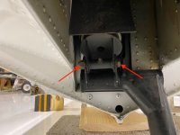
NOTE and this is REALLY IMPORTANT
The clevis (fork) is NOT symmetrical. One side has a deeper cut than the other. The arrows point to where the bottom of the clevis opening is. The deep opening has to go next to the lever arm. If you get it backwards the bottom of the lever arm will hit the clevis saddle and probably cause it to crack and fail. I recently checked a friends floats and found both clevises were 180 degrees out. This is NOT in the manual but certainly should be. (Amy?)
Addendum
Your system might look different depending on what model (new or older) set of floats you have. See below.

The proximity switch are either clamped to the ram or they are attached to the wall of the float like this. This is the newer style I think.

If you have the newer style your clevis pin will look more like this. #1 is the machined clevis pin #2 is the proximity switch (reed switch)
#3 is a cylinder magnet. It is held in place by the set screws (#4). This allows you to adjust it (the magnet) in and out to get it close enough to the reed switch to activate it. No need to take the set screws and magnet out. The clevis, spring, and lever arm labels are just there to orient you to understand what you are seeing. You may have to pump the hydraulics by hand to move this assembly (lever arm) to get it to a place where you can get it apart without hitting the reed switch. Try HARD not to damage anything. Parts are very expensive. Unless you are replacing the hydraulic ram do not loosen the clevis.

The nut we are looking for next is at the bottom of the Hydraulic ram where the arrow is. Put your finger on it and find it. Then read the next step.

Next we are going to remove this 12" long bolt/axle doohicky, thingamabob. The ram sits on this right where the arrow is. See above photo. So get a 1/2" socket with a small 1" extension and feel your way to the bottom of the ram and remove this nut. (The manual erroneously calls it a bolt). Now you can slide the ram off the bolt and move it out of the way. No need to remove the hydraulic line.
Next you will need a 3/4" wrench and a 3/4" socket on a short extension. You will be removing the 3/4" nut that is now accessible because you got the 1/2" nut and ram off. You will have to use the socket on the inside side of the float. I know that normally we try to turn the nut and hold the bolt but in this case you will use the wrench on the ram side of the float and you will use the socket to turn the bolt/axle. Through the opening in the little bulkhead in there. Once you have the nut off we will be removing the bolt. You might need to go under the float and spray some penetrating oil on the openings that this bolt goes through. You will see it once you get down there. It can be a bear to get out unless you used that good grease noted above last season. Then it just slides right out. You might be able to use a series of dowels 1", 2", 3" long etc to tap the bolt out. It is a tight fit down in the opening.

It will help to wiggle this tube while you are trying to pull that axle out. You will be laying on the float, trying to take the pressure/weight off of the axle by wiggling this, while twisting and pulling the axle. After you get this out take a break. You will need it.....LOL. This is the hardest part.
If you still can't get the bolt out, try loosening the side plate nut/bolts (4 on each side). You will need to pull the lever arm out, that will free up the shock donut assembly, so you can move it around to get to the side plate nuts/bolts. See below on removing the lever arm.

Now we will remove the two bolts here. It is easiest to use a long extension on the socket. This is the lever arm. As mentioned above you might have to remove these to get the clevis pin out of the clevis and lever arm assembly in the steps above.

Now we can pull the retract lever arm out. This will cause the top of the mechanism to drop down. It will probably make a racket (unless it is binding due to lack of maintenance and grease and will not move). Its OK. Let it drop. You will be moving that part of the mechanism around in order to get to the 8 bolts that hold the sides on.

Now get your 3/4" wrench and socket and lay on the floor. We will remove this bolt. That will then allow you to remove the axle assembly.

The axle assembly looks like this.

This is the grease zerk assembly that is in the end of the axle. It may or may not come out. It can be a challenge to get out. It has 2 "O" rings that you might need to replace. Basically if it does not come out I would not mess with it. It is held in place by the cotter pin that holds the axle wheel nut on.

Next we will remove the main assembly. Looks like this. There are four 3/8" bolts on each side. So you get to remove 8 of the little suckers. You will be once again laying on the float. It is easiest to hold the wrench on the inside and use the socket on the nut. Keep up with the washers. All the bolts are the same length but the thickness of the metal they go through varies based on the doublers so they have different numbers of washers to make sure the nut does not bottom out on the threads. The unit will come out the bottom when all 8 bolts are out (4 per side)
This is a
MESSY NASTY job. Be sure to wear a shirt you want to throw away when you are done.
Next we will remove the two bolts & nuts as shown above. Now you can take things apart.

You will have to remove the outer two grease zerks to get the axle out. No need to remove the middle one. I don't take the donuts apart. I just clean things and inspect. If your donuts are cracked you will need to remove and replace.
So now we clean the heck out of everything. Inspect for wear and cracks and stuff like that. Reassemble using the good grease and install using the reverse order.
VERY IMPORTANT When you put the side panels back in just put the top bolt on each side and leave the nut loose. Then put the lever arm through to line up those holes, (no need to thread it through the donut assembly right now, we are just using it to line things up) Next put that long 12" bolt through the bottom holes and thread it through the axle assembly when you do. With these two bolts threaded through it lines things up. Now put in the remaining 6 side plate nuts and bolts and tighten all 8 up. There are a few more notes on how to do this a few post below this.
You might need a small bullet to get the clevis pin back in the retract lever arm. You might need to move the hydraulic ram via the standby hydraulic pump to help line things up to get the lever arm (which is now threaded through the donut shock assembly) attached to the ram.
You will also be looking at the wheel bearings and races, replacing as necessary, repacking etc. It is also a good time to replace the brake shoes. Here is a link to that info
https://www.supercub.org/forum/show...g-a-Javron-Cub&p=651394&viewfull=1#post651394
More to follow
Hope this helps
Bill