• If You Are Having Trouble Logging In with Your Old Username and Password, Please use this Forgot Your Password link to get re-established.
  • Hey! Be sure to login or register!

FarmBoy's Oil Temp Thread

Pete,
This my have been brought up somewhere in this thread. Have you looked at the pitch on both props from the center out to the end of the cowl. may be the first 20" have a different pitch, hence changing air flow into the cowl. Not talking about the total pitch just the first section.
Chip
 
pb,
This is a picture of the nose opening grill on the Stinson 108: https://www.ebay.com/itm/Stinson-10...8-8541008-7-/111413578799?hash=item19f0c44c2f

Notice that the horizontal bars are an airfoil shape which are angled to capture the rotating air mass from the propeller. The right side is designed to capture the air from above. The opposite side captures the air from below. Try installing directional vanes across the test nose piece which you showed us a couple of days ago.
 
A manifold pressure gauge and CHT gauge would be excellent tools to help work through this. We discussed the lack of these tools a lot, although perhaps in the previous thread (c90 catto prop).

While load on the engine is a concern, as Oliver mentioned, climb props run cooler as they are putting less load on the engine. Essentially you have shifted down the gearing so the engine doesn't work as hard in cruise. An easy load test is look at WOT rpm in trimmed level flight. If you turn a higher rpm with one prop vs another, the higher rpm prop is putting less load on the engine than the one turning lower rpm. This is the case in my situation. More WOT rpm, less load on engine.

The Sensenich is a 76, replacing a McCauley 71. All together a different prop, both in blade shape, chord, and diameter. Therefore we don't have any idea of what type of airflow/turbulence/etc has changed around the cowl, both inside and outside. Oil temp permitted or acceptable "ranges" aside, the one hard data point we have is a change in oil temp with the prop change. All other data stays constant - day/temp/flight parameters.

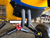
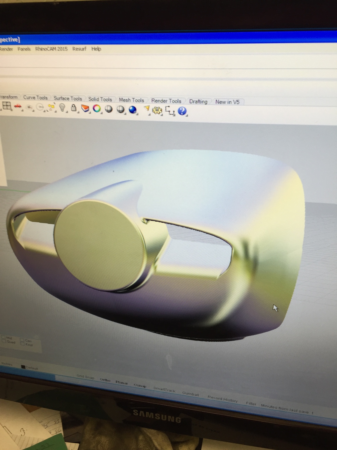
Cowl door flares (a'la radial flaps), louvered vents, and a redesigned lower cowl panel all have potential to create the suction desired to increase cooling airflow. The challenge is to first find a solution that works, decide if it's an acceptable design change, and then incorporate the best version of it. As always simple and unobtrusive solutions are often better than large physical changes. As Cubcrafters seems to be the ones that have ramped up with a hot engine to better cowl design history, I often look at the changes they have made. Increased door sizes, cowl flaps, louvered gill vents, ramp inlets, secondary plenums and lower cowl design changes, not in any particular order.

I think I've posted this before, but some of the things I plan to test, alone or in conjunction with others, in no particular order -
~ inlet ramps
~ adding rounded firewall edges to smooth airflow
~ temporary VG's on cowl doors and lower cowl to see if it mixes with exit air and helps increase exit velocity
~ temporary cowl door flares/flaps to create greater low pressure area
~ larger lower cowl panel, creating greater and longer aft opening
~ larger or redesigned chin spoiler

In addition to keeping the manometer installed during testing, I have a chinese CHT monitor and canadian thermocouples coming to get more data. But, the slow boat from overseas and up north means end of March perhaps before they arrive.

So, we work towards a solution, if not a better understanding of the change. While we may never truly understand the complex differences without a wind tunnel and a few aerodynamicist's, a solution that works we will find. You can count on that. I was just hoping someone knew Roy Lopresti personally and would give him a call. ha!

pb

Tom : My cowl doors are 2" at the wide point, so they are wider than I thought originally.

Peter,

Have you checked your baffles as well? I can't remember if we'd already talked about that. I was thinking about that this morning - it might be that you're leaking so much air that small improvements may not be measurable with the manometer.

check the pictures on page 1 and 2 of this thing that Stewart posted up a while back to see what I'm talking about. Also, close your cowl up and hang a drop light behind your engine. Look through your cowl inlets - can you see light passing through the baffle seals to the cowling?

http://www.n91cz.net/Interesting_Technical_Reports/106-111_BuildingBasics.pdf
 
Chip, yes, we believe that to be the case. I tested secondary "pressure blades" behind the spinner to help in that area but it fatigued quickly rotating in front of the cowl and then over the top of the cowl and I had to remove it.

Pete, the inlet nostrils are tape covered foam - adding vanes would not be possible in those. But I think about the turbulence possibilities hitting the square face of the cylinders, so I've got some ramps to install to help direct the flow up over the top.

Cam, we have, and yes, baffles are all good.
 
pb,
The ramps do help with the flow of the air which is already inside the cowl. The vanes grab more air from outside forcing a lager volume in through the openings. Instead of some of the outside air bouncing off and away of the nose bowl, the vanes grab and deflect it inside.

The ramps and the vanes are performing two separate functions.
 
Peter,
loving your “nostril” experiment, disapointing it didn’t produce better results.
checking out your installed “seaplane lip”, it appears on your to do list as well. I went overboard on the lip and made it as big as space would allow, even cut back lower cowl material to increase opening and added a lip to the lip for good measure.
kind of gave up on the manometer as s diagnostics tool, but the new lip did affect lower cowl pressure as well as noticible CHT drop. I've since cleaned up the install a bit since it’s a keeper.
just a thought.

Doug
 

Attachments

  • C0498538-B3A3-4FFA-A522-923416C772FC.jpg
    C0498538-B3A3-4FFA-A522-923416C772FC.jpg
    65.4 KB · Views: 130
Last edited:
Interesting.

I didn’t cut back the opening, but I did enlarge the lower vent as you did. Sadly it did not make any difference, and I almost wonder if it made it worse. My only thought since then is that while it should have a greater draw from the low pressure, perhaps the opening is not large enough. There is a lot of items that can interrupt air flow in that area, so as you did perhaps it needs the lower cowl opening cut back.

IMG_0640.JPG

IMG_0641.JPG

The other thought I had was to add two naca inlets or old fashioned scoops, one on each side of the lower cowl, and duct it to the oil tank for cooling. Use a shield as someone mentioned earlier to flow it down under the tank and out the back.


Transmitted from my FlightPhone
 

Attachments

  • IMG_0640.JPG
    IMG_0640.JPG
    84.5 KB · Views: 139
  • IMG_0641.JPG
    IMG_0641.JPG
    194.5 KB · Views: 141
Dang!
and I thought mine was big.
maybe try a more drastic angle and chop it off so it’s more abrupt.
who knows? A lot of dark magic going on under the cowl.
I’ve been using Kydex to help execute some of my crazy ideas, cold and heat forms well into scoops and other shapes.
Cuts easily, durable too.
 
Dang!
and I thought mine was big.
maybe try a more drastic angle and chop it off so it’s more abrupt.

Exactly. Lol.

In testing I added and subtracted a flared lip without seeing a change. But the size should create a serious low pressure...

That said, I believe Scott Reviour told me that his worked best with a smaller lip, so it’s more trial and error perhaps.

I’ll have some aluminum back in stock next week, I might try a different shape lower cowl with a larger aft cutout as you mentioned. That way I can always go back to the stock original which hasn’t been chopped up yet.

Part of that idea comes from an old c90 oil temp thread where Steve Pierce talked about adding the Cessna 150 cowl vent, which is really a quite large lower cowl intake scoop.

Pb


Transmitted from my FlightPhone
 
Why not try an adjustable cowl flap? Piano hinge on lower aft cowl, clearance for exhaust or whatever sticks down, and control cable from the panel. Years ago they made then in Alaska for winter ops but of course this is the reverse. That way you could note any changes with deflection.

Gary
 
Only because I have some data points already. Stock, spoiler, spoiler with lip, flap, flap with lip.

Next thing i think is either open up the cutout, or introduce additional air.


Sent from my iPhone using SuperCub.Org
 
They can be installed as you know. Factory cooler replaces left rear blocking plate with two holes underneath with oil flow between them. The oil filter adapter uses those holes for flow. Drill and tap that aluminum plate..or make a steel replacement with fittings. Put a cooler on the firewall or ??? and feed it with air. That's unless you like fussing with cowling and air hoping your CHT's, exhaust valve guides, or crank bearings aren't the problem.

Edit: I see the -8 and -8F don't have that cooler pad P/N 35033. Is yours that model?

Gary
 
Last edited:
I haven’t seen a simple install on a -8, and have no firewall space for it. So, looking for other solutions until that’s the only feasible one left. In the short term this is the affordable direction.
The prop causes the change . Hard to say that any internals contribute.


Sent from my iPhone using SuperCub.Org
 
So, I’m not real smart on this stuff, but if the prop/spinner is causing this issue, then wouldn’t going after the air intake be the way to go?
 
Well, air can’t compress much at 85 inside a cub cowl, so you have two choices, either force it in or suck it out. I’ve tried both so far with not great results, so apparently I’m not real smart on this stuff either. [emoji23]


Sent from my iPhone using SuperCub.Org
 
Was the spinner installed when you flew it in this condition? That can make a difference.

This is an example of a propeller with added cuffs. I have seen this type of cuff which was molded out of a hard rubber.
f21959fa66b01ea9bc93f6227d60cb89--aircraft-engine-military-aircraft.jpg


Another one. This is the type which I saw.

300px-Vultee_L-1A_Vigilant_USAF.jpg
 
Ive looked quite a bit at prop cuffs Pete, which helped lead me to the idea of an “inside” pressure prop mounted between the prop and the flange. If it was made of carbon fiber it would probably have the rigidity to withstand the stresses, but the aluminum fatigued and threw a side after 15-20 minutes of testing.
(The pressure difference between rotating in front of the cowl vs over the top of the cowl caused it to work a bend until it cracked)

I don’t have enough engineering experience to add cuffs to blade barrels.

Regarding spinner, tried it both ways.


Sent from my iPhone using SuperCub.Org
 
Notice the scoops over the cowl openings on this Bellanca.

Yes, inlets scoops or fences were the idea many have used it seems, and what I was testing by attaching the nostrils. Without a change, I've removed them again.

Here's a photo from last october of the progression to the pressure prop theory I mentioned in the last post.
fullsizeoutput_146d.jpeg
 

Attachments

  • fullsizeoutput_146d.jpeg
    fullsizeoutput_146d.jpeg
    107 KB · Views: 134
I wouldn't mess with the blade cuffs either. Just wanted to show you how it has been done in the past. Too many variables to take into consideration with any one failure having the potential for a catastrophe.
 
For what it is worth, I just installed my Sensenich ground adjustable prop and spinner. It is 76”. No change in oil or cylinder head temps. Taylorcraft F21. Lycoming 0-235 no oil cooler. Oil temps still run low.

Jim
 
This is the setup on my 0-200 cub. I cut the bottom of the cowl to try to get more airflow through because of high oil temperature . It got the cylinder temperature down to 400 but still high oil temps even with the oil cooler. Makes me think I'm not still getting enough air through it. IMG_0619.JPGIMG_0620.JPGIMG_0622.JPGIMG_0624.JPG


Sent from my iPhone using SuperCub.Org mobile app
 

Attachments

  • IMG_0619.JPG
    IMG_0619.JPG
    207.6 KB · Views: 121
  • IMG_0620.JPG
    IMG_0620.JPG
    215.7 KB · Views: 124
  • IMG_0622.JPG
    IMG_0622.JPG
    187.4 KB · Views: 133
  • IMG_0624.JPG
    IMG_0624.JPG
    596.5 KB · Views: 128
Doug, why are your cowl doors flush with the boot cowl? I’ve never seen a cub that didn’t have the 2 to 3 inch “cheek” opening there for cooling.
IMG_0491.JPG


Sent from my iPad using SuperCub.Org mobile app
 

Attachments

  • IMG_0491.JPG
    IMG_0491.JPG
    105 KB · Views: 92
When I have moments I'm looking at a larger opening in the bottom cowl. Finally found a photo of one with the bottom opening and spoiler halfway to the carb... figure he knew something I haven't found yet.

fullsizeoutput_25b6.jpeg

riH7+YART7qkFyvhxIOzzg.jpg
 

Attachments

  • riH7+YART7qkFyvhxIOzzg.jpg
    riH7+YART7qkFyvhxIOzzg.jpg
    121.8 KB · Views: 110
  • fullsizeoutput_25b6.jpeg
    fullsizeoutput_25b6.jpeg
    46.9 KB · Views: 397
The idea was to try to make it go faster so built it like a T craft, champ pacer etc. didn't work going to have to rebuild. If you notice in the picture the firewall is set back so if I want to use a 0-320 it won't be so nose heavy and I think that may block some of the air going out the bottom


Sent from my iPhone using SuperCub.Org mobile app
 
Back
Top